Axial-flow wind wheel

An axial flow wind and wind wheel technology, which is applied to the components of pumping devices for elastic fluids, non-variable-capacity pumps, pump components, etc. The work area of ​​the wheel blade 12 is solved, so as to increase the work area, reduce the turbulence intensity and turbulent noise, and improve the work efficiency.

Inactive Publication Date: 2012-08-22
GD MIDEA AIR-CONDITIONING EQUIP CO LTD
View PDF5 Cites 10 Cited by
  • Summary
  • Abstract
  • Description
  • Claims
  • Application Information

AI Technical Summary

Problems solved by technology

When the air flow passes through the rotor blade 12 at a certain angle of attack, due to the existence of an inverse pressure gradient, the air flow will begin to generate boundary layer separation at the region 29 near the trailing edge 28 of the suction surface 21, thereby reducing the actual strength of the rotor blade 12. The working area reduces the working efficiency of the wind rotor; at the same time, the airflow forms turbulent vortices 30 of various scales in the separation area, and continuously falls off from the tail edge 28 of the wind rotor to form a wake shedding vortex street, which not only enhances the turbulence intensity , will generate broadband turbulent noise at the same time

Method used


Image

  • Axial-flow wind wheel
  • Axial-flow wind wheel
  • Axial-flow wind wheel

Examples


Embodiment 1

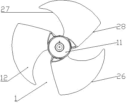
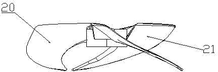
[0028] like Figure 4 and Figure 5 As shown, this embodiment includes a hub 101 and three wind rotor blades 102 arranged around the hub 101; the wind outlet surface of the wind rotor blade 102 is the pressure surface 120, and the wind suction surface of the wind rotor blade 102 is the suction surface 121; The outermost edge of the blade 102 along the radial direction is a blade tip 126 , and the blade tip 126 connects the leading edge 127 of the wind rotor blade 102 on the wind inlet side and the trailing edge 128 on the wind outlet side. A plurality of through holes 200 are provided in the region of the trailing edge 128 of the rotor. The shape of the through hole 200 is a circular or non-circular straight through hole or oblique through hole. The distribution positions of the through holes 200 are arranged vertically and horizontally according to regular rules; the aperture range of the through holes 200 is 0.1mm-300mm; all the through holes 200 are close to the area of ​...

Embodiment 2

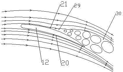
[0030] Embodiment 2: as Figure 6 As shown, several through holes 200 are designed in the trailing edge area of ​​the wind rotor blade 102 . The circumferential dimension of the through hole 200 gradually increases from the center of the rotor to the outer edge of the rotor. Other structural features of the through hole 200 are the same as those in the first embodiment. The effect is that during the rotation of the wind rotor, the linear velocity of the fluid bypassing the circumferential section of the wind rotor gradually increases from the center of the wind rotor to the outer edge of the wind rotor, and the boundary layer separation zone at the trailing edge of the suction surface of the wind rotor also gradually increases. Therefore, the design of the through hole method in this embodiment is not only beneficial to the part of the fluid in the boundary layer of the pressure surface of the wind turbine to flow to the trailing edge area of ​​the suction surface through the...

Embodiment 3

[0031] Embodiment 3: as Figure 7 As shown, a through hole 200 is designed in the trailing edge region of the wind rotor blade 102 . The through hole 200 is located at the trailing edge of the rotor blade 102 near the outer edge of the rotor. Other structural features of the through hole 200 are the same as those in the first embodiment. The effect is that: during the rotation of the wind rotor, the linear velocity of the fluid passing around the circumferential section of the wind rotor is relatively large at the outer edge of the wind rotor, and the separation of the boundary layer at the trailing edge of the suction surface of the wind rotor is relatively slow near the outer edge of the wind rotor. Obviously, the design of the through hole method in this embodiment can not only effectively suppress the separation of the boundary layer at the trailing edge of the suction surface of the wind rotor, increase the actual work area of ​​the wind rotor, and improve the working ef...


PUM


Abstract

The invention relates to an axial-flow wind wheel comprising a hub which is connected with a motor and a plurality of wind wheel blades which are arranged around the hub; each wind wheel blade comprises a wind wheel front edge on a wind inlet side and a wind wheel tail edge on a wind outlet side; and the axial-flow wind wheel is characterized in that through holes are arranged in a wind wheel tail edge area. According to the axial-flow wind wheel, due to the arrangement of through holes in the wind wheel tail edge area, when the wind wheel rotates, as the pressures of a pressure surface and a suction surface of the wind wheel are different, some fluid in a border layer of the pressure surface of the wind wheel passes through the through holes and flows to the tail edge area of the suction surface, the separation of the border layer of the suction surface is delayed, the actual work area of the wind wheel is increased, so that the working efficiency of the wind wheel is effectively improved; and simultaneously, the production and the fall-off of turbulent vortex in the separation area of the border layer of the suction surface are suppressed and damaged, so that the turbulence intensity and the turbulence noise of the border layer are reduced.

Description

technical field [0001] The invention relates to an axial-flow wind rotor, in particular to an axial-flow wind rotor which increases the working area of ​​the wind rotor blades, reduces turbulent flow intensity and reduces turbulent noise by suppressing separation of the turbulent boundary layer at the trailing edge of the wind rotor. Background technique [0002] Generally, the axial flow wind wheel is a device that is driven to rotate by a motor to drive the gas to blow air in the axial direction. Axial flow wind rotors are not only suitable for home appliances such as air conditioners, electric fans, and refrigerators, but are also widely used in industrial fields such as computers, aerospace, and ships. [0003] Attached below figure 1 and figure 2 To illustrate the prior art of the axial flow wind wheel. [0004] As shown in the figure, the existing axial flow rotor 1 includes a hub 11 and several rotor blades 12 arranged around the hub. The characteristics of the f...

Claims


Application Information

Patent Timeline
Patent Type & Authority Applications(China)
IPC IPC(8): F04D29/38
CPCF05D2240/304F04D29/682F04D29/684F04D29/384
Inventor 郭双喜任志洁苏炳超
Owner GD MIDEA AIR-CONDITIONING EQUIP CO LTD
Why Eureka
Try Eureka