A switch door signal measurement circuit

A technology for measuring circuits and gate signals, which is applied in the field of signal measurement, can solve problems such as increased power consumption, increased equipment size, and inability to accurately design, and achieves the effects of accurate measurement, reduced volume, improved measurement accuracy and system reliability

Active Publication Date: 2017-06-27
BEIJING INST OF ASTRONAUTICAL SYST ENG +1
View PDF6 Cites 0 Cited by
  • Summary
  • Abstract
  • Description
  • Claims
  • Application Information

AI Technical Summary

Problems solved by technology

The traditional measurement method is built by combining gate circuits. The timing margin of the circuit can only be controlled by the chip, and the timing cannot be precisely designed, and each channel needs many combination circuits to realize. For the multi-channel switch to be measured required by the model The gate signal requires a large number of gate circuit devices to realize, which will lead to increased equipment size, increased power consumption, and decreased system reliability.

Method used


Image

  • A switch door signal measurement circuit
  • A switch door signal measurement circuit
  • A switch door signal measurement circuit

Examples


Embodiment Construction

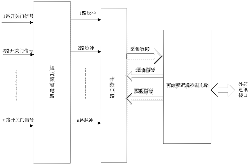
[0017] like figure 1 As shown, the present invention proposes a switch gate signal measurement circuit, including an isolation conditioning circuit, a counting circuit and a programmable logic control circuit;

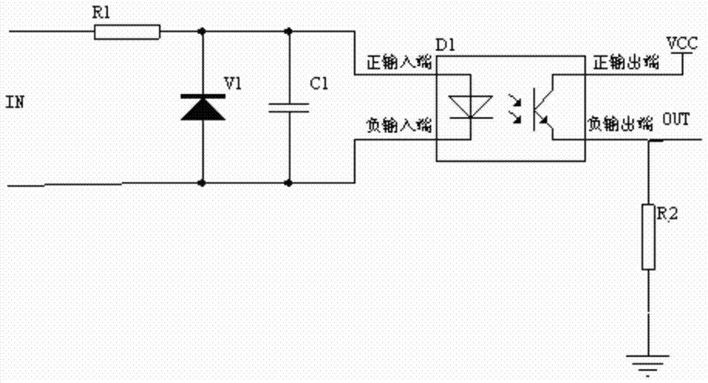
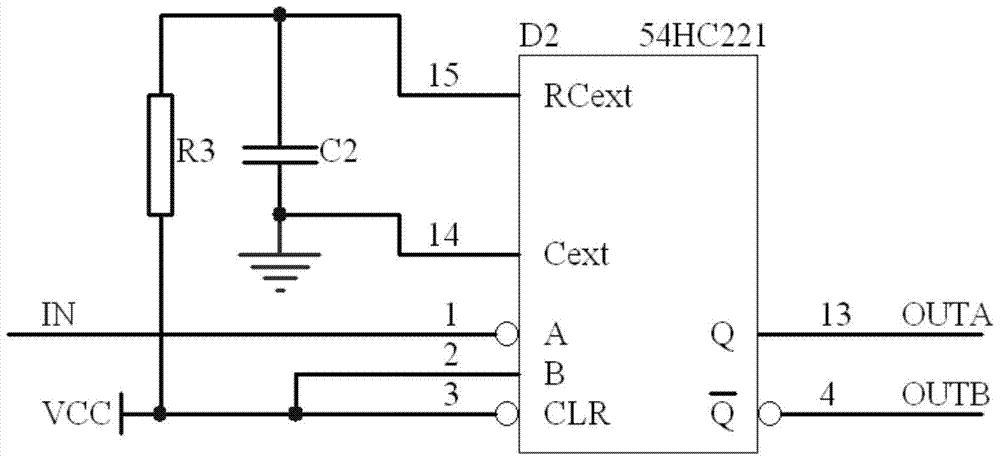
[0018] The isolation conditioning circuit includes n-channel isolation circuits and n-channel monostable pulse conditioning circuits; the isolation circuit collects n-channel switch gate signals, isolates and filters the collected n-channel switch gate signals, and then isolates and filters each channel The switch gate signal is converted into a pulse signal with a fixed pulse width, and each converted pulse signal is output to the monostable pulse conditioning circuit; the monostable pulse conditioning circuit converts each pulse signal output by the isolation circuit into a fixed pulse width The pulse signal; the counting circuit collects and counts each pulse signal output by the isolation conditioning circuit under the control of the programmable logic control circ...


PUM


Abstract

The invention discloses a switch gate signal measuring circuit. The switch gate signal measuring circuit comprises an isolating and conditioning circuit, a counting circuit and a programmable logic control circuit. The isolating and conditioning circuit acquires switch gate signals and isolates and filters the acquired switch gate signals, and each path of isolated and filtered signals are converted into pulse signals with fixed pulse width; the counting circuit is controlled by the programmable logic control circuit to acquire and count each path of pulse signals output by the isolating and conditioning circuit; the programmable logic control circuit sends control signals and gating signals to the counting circuit and sends the counting result of the counting circuit to an external communication interface. According to the switch gate signal measuring circuit, a traditional combined gate circuit is replaced with the programmable logic control circuit, and thus the size and the weight of a switch gate signal measuring device are reduced; meanwhile, the switch gate signals can be accurately measured by accurately controlling the time sequence of the circuit and the counted number, and the measurement accuracy is improved.

Description

technical field [0001] The invention relates to a switch door signal measuring circuit, which belongs to the field of signal measurement. Background technique [0002] The door switch signal is a signal that the telemetry system often needs to measure, and it is usually the inertial group pulse signal sent by the control system. The traditional measurement method is built by combining gate circuits. The timing margin of the circuit can only be controlled by the chip, and the timing cannot be precisely designed, and each channel needs many combination circuits to realize. For the multi-channel switch to be measured required by the model The gate signal requires a large number of gate circuit devices to realize, which will increase the size of the equipment, increase the power consumption, and reduce the reliability of the system. [0003] Therefore, in order to meet the measurement requirements of door opening and closing signals, it is urgent to design a new door opening an...

Claims


Application Information

Patent Timeline
Patent Type & Authority Patents(China)
IPC IPC(8): G05B19/05
Inventor 彭旭锋赵卫军王星来赵雪梅祝京王昕
Owner BEIJING INST OF ASTRONAUTICAL SYST ENG
Why Eureka
Try Eureka