Supercharge Your Innovation With Domain-Expert AI Agents!

Gas turbine with exhaust gas diffuser and support ribs

A gas turbine and diffuser technology, which is applied in gas turbine installations, machines/engines, mechanical equipment, etc., can solve problems such as restricting the working mode of gas turbines and afterburners

Inactive Publication Date: 2016-03-02
SIEMENS AG
View PDF4 Cites 0 Cited by
  • Summary
  • Abstract
  • Description
  • Claims
  • Application Information

AI Technical Summary

Problems solved by technology

When applying the afterburner, the ability to generate flashback through backflow may limit how the combined gas turbine and afterburner works

Method used


Image

  • Gas turbine with exhaust gas diffuser and support ribs

Examples


Embodiment Construction

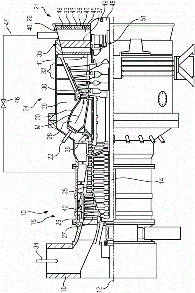
[0013] figure 1 A partial longitudinal section of a stationary gas turbine 10 is shown. The gas turbine 10 internally has a rotor 14 mounted in rotation about an axis of rotation 12 , which is also referred to as a turbine rotor. Along the rotor 14 are the suction housing 16 , the axial turbocompressor 18 , the toroidal annular combustion chamber 20 with a plurality of burners 22 arranged rotationally symmetrically to one another, the turbine unit 24 and the turbine exhaust housing 26. A turbine exhaust gas distributor, not shown in further detail, is connected to the turbine output housing 26 of the gas turbine 10 . These two components are part of the gas turbine exhaust diffuser 21 . Instead of an annular combustion chamber, the gas turbine can also be constructed with a plurality of tubular combustion chambers.

[0014] The axial turbocompressor 18 comprises a ring-shaped compressor channel with compression stages formed successively in cascade fashion in it, formed of...


PUM


Abstract

The present invention involves a gas turbine (10), which has an exhaust gas diffuser (21) connected to the turbine unit (24), which is connected to the turbine unit (24).The boundary limit and there are multiple overlapping ribs (35) that extends to the internal extension for fixing the gas turbine (10) radial bearing (51).A exhaust pipe (47) ended on the exhaust gas diffusion (21), which connected to the compressor (18) of the gas turbine (10) of the gas turbine (10) of the exhaust pipeline (21).In order to compensate at least partially to compensate the support rib (35) errors in some load running, the support rib (35) has a hub (48) on its internal end.It is used to discharge the exhaust air to another opening in the diffuser channel (49).

Description

technical field [0001] The invention relates to a gas turbine with an exhaust gas diffuser connected to a turbine unit, the diffuser channel of which is delimited on the outside by a wall and on which a plurality of inwardly extending bars for fastening the gas turbine are provided. The hollow support rib of the radial bearing, wherein at least one exhaust duct for the exhaust air, including the pipeline, terminates on the exhaust gas diffuser on the outflow side, the end of the inflow side of the exhaust duct is connected to the gas turbine compressor connection. Background technique [0002] Gas turbines and their mode of operation are known very well from the widely available prior art. The gas turbine always includes an exhaust gas diffuser as part of the exhaust gas path, through which the exhaust gas flowing out of the gas turbine can be conducted further. If the gas turbine is set for a simple cycle, known in English as SimpleCycle, then the exhaust gases are either...

Claims


Application Information

Patent Timeline
Patent Type & Authority Patents(China)
IPC IPC(8): F01D25/30F02C6/08
CPCF01D25/30F02C6/08
Inventor 马克·布勒克托比亚斯·布哈尔
Owner SIEMENS AG
Features
  • R&D
  • Intellectual Property
  • Life Sciences
  • Materials
  • Tech Scout
  • Unparalleled Data Quality
  • Higher Quality Content
  • 60% Fewer Hallucinations
Learn More