Supercharge Your Innovation With Domain-Expert AI Agents!

Clamping device for automatic tin dipping machine

A technology of clamping device and tin dipping machine, which is applied in auxiliary devices, metal processing, metal processing equipment, etc.

Active Publication Date: 2014-11-19
ANHUI HEHAN OPTOELECTRONICS TECH
View PDF9 Cites 3 Cited by
  • Summary
  • Abstract
  • Description
  • Claims
  • Application Information

AI Technical Summary

Problems solved by technology

[0003] The purpose of the present invention is to solve the problem of poor versatility of the tin dipping fixture used to clamp the transformer on the automatic tin dipping machine in the prior art, and to provide a tin dipping fixture

Method used


Image

  • Clamping device for automatic tin dipping machine
  • Clamping device for automatic tin dipping machine
  • Clamping device for automatic tin dipping machine

Examples


Embodiment 1

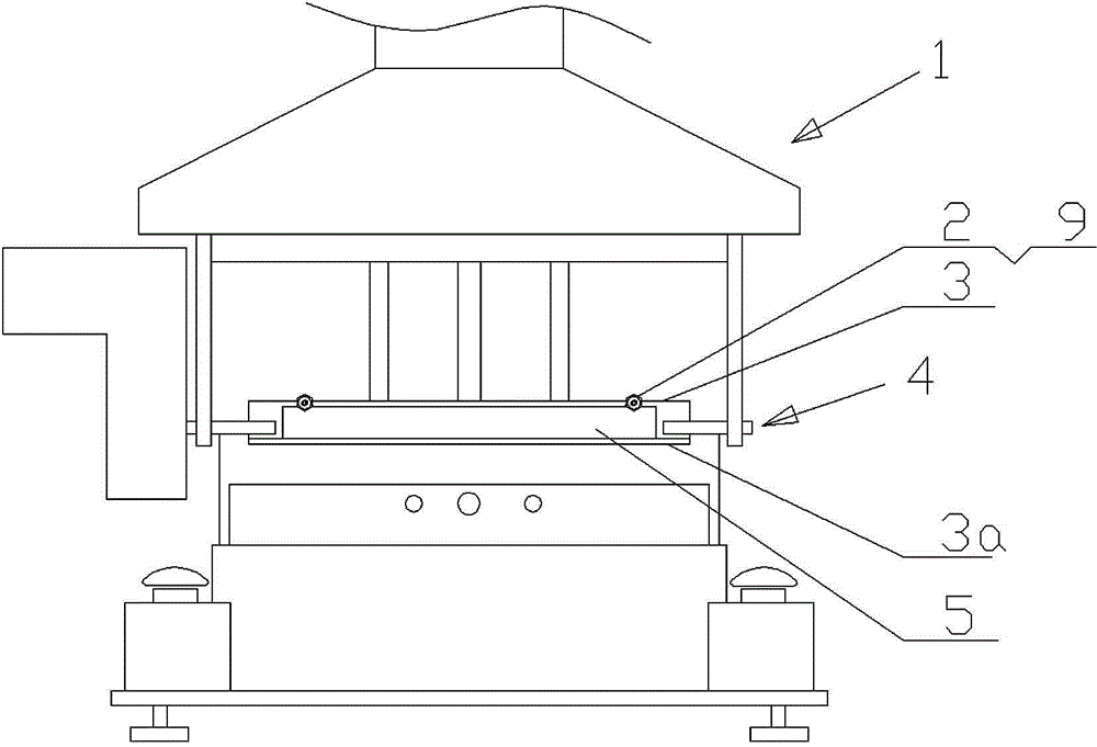
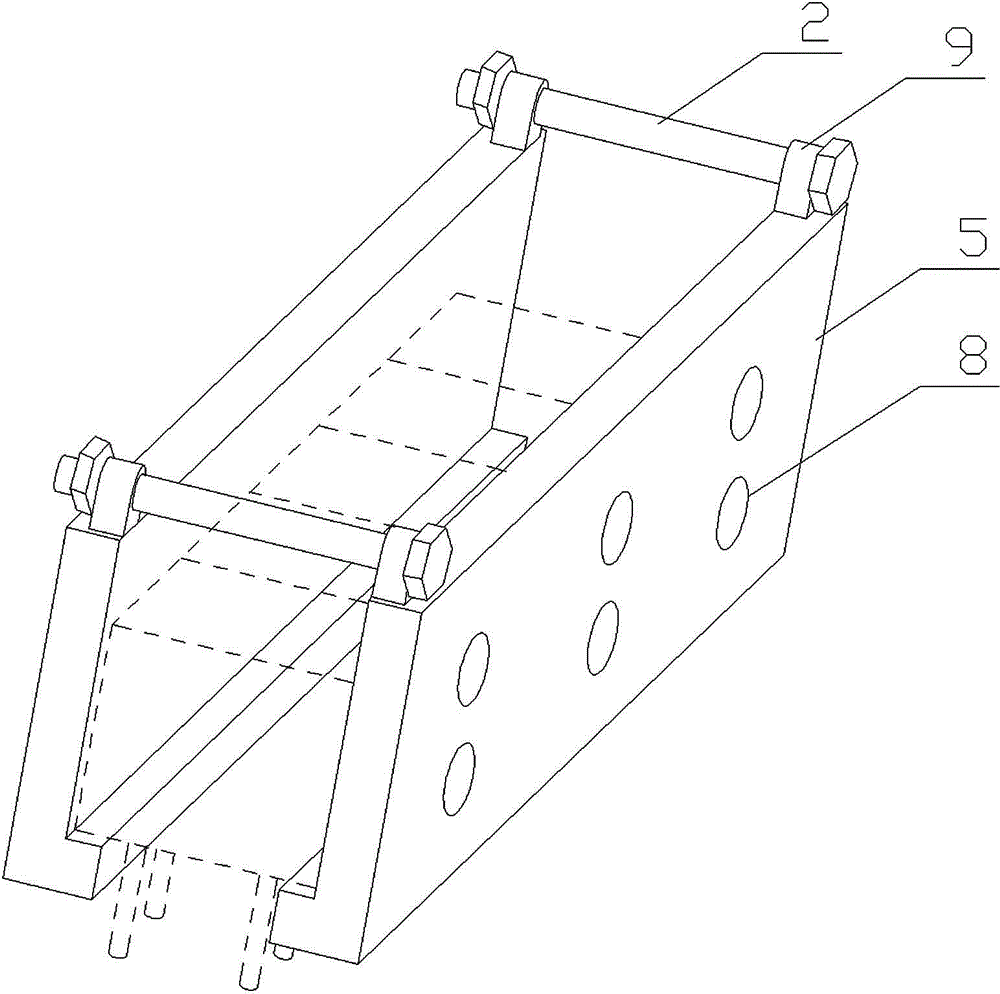
[0017] Such as figure 1 and figure 2 As shown, a clamping device for an automatic tin dipping machine provided by the present invention includes a jaw mechanism 4 arranged on the body 1 of the tin dipping machine. A positioning boss 3a is provided along its horizontal direction, and two symmetrically arranged L-shaped splints 5 are arranged on the positioning boss. A connecting seat 9 is respectively arranged at a symmetrical position on the top of each splint, and the connecting seats corresponding to the L-shaped splint pass through The adjusting bolts 2 are matched and connected, and one side of one of the L-shaped splints is adsorbed on the turnover plate by a group of powerful magnets 8 .

Embodiment 2

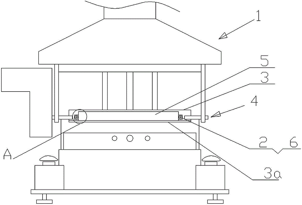
[0019] Such as image 3 , Figure 4 and Figure 5 As shown, a clamping device for an automatic tin dipping machine provided by the present invention includes a jaw mechanism 4 arranged on the body 1 of the tin dipping machine. A positioning boss 3a is provided along its horizontal direction, and two symmetrically arranged L-shaped splints 5 are arranged on the positioning boss. Both sides of each L-shaped splint are respectively provided with chute 5a, and a pair of ball springs 7 are arranged at the bottom of the chute. , there is a sliding block 6 in the chute, the bottom of the sliding block is provided with a limit groove 6a that cooperates with the ball spring, and the sliding blocks 6 corresponding to the splint 5 are connected by adjusting bolts 2, and one of the L One side of the splint is adsorbed on the turnover plate 3 by a group of powerful magnets 8 .


PUM


Abstract

The invention relates to a clamping device for an automatic tin dipping machine. The clamping device comprises a clamping jaw mechanism (4) on a tin dipping machine body (1), and a turning plate (3) is connected to the clamping jaw mechanism. The clamping device is characterized in that two symmetrically-arranged L-shaped clamping plates (5) are connected to one side of the turning plate, the clamping plates are matched and connected through adjusting bolts (2), and one side of one L-shaped clamping plate is attracted to the turning plate through a set of strong magnets (8). The clamping device has the advantages that the universality on a tin dipping clamp for clamping a transformer on an automatic tin dipping machine in the prior art is high, the development time of production design is shortened, and the production cost of products is greatly lowered.

Description

technical field [0001] The invention relates to a clamp, in particular to a clamping device specially used for clamping a transformer on an automatic tin dipping machine. Background technique [0002] In the manufacturing process of the transformer, an automatic tin dipping machine is often used to dip the connecting terminals of the transformer into tin to improve its conductivity and the firmness of the connection. Before producing the transformer, it is necessary to specially design a fixture according to the actual transformer specifications, so as to facilitate the clamping of the transformer and improve the efficiency of tin immersion. Due to the wide variety of transformers and the poor versatility of the existing fixtures, it is often necessary to design and develop fixtures of different specifications and sizes because the original fixtures cannot be used in production to meet their needs, which not only consumes a long time for production design and development. ,...

Claims


Application Information

Patent Timeline
Patent Type & Authority Applications(China)
IPC IPC(8): B23K3/08
CPCB23K1/08B23K3/087B23K2101/36
Inventor 夏云
Owner ANHUI HEHAN OPTOELECTRONICS TECH
Features
  • R&D
  • Intellectual Property
  • Life Sciences
  • Materials
  • Tech Scout
  • Unparalleled Data Quality
  • Higher Quality Content
  • 60% Fewer Hallucinations
Learn More