Supercharge Your Innovation With Domain-Expert AI Agents!

Laser machining machine table and correction method thereof

A laser processing machine, laser processing technology, used in laser welding equipment, metal processing equipment, manufacturing tools, etc., can solve the problems of waste, correction of steel plates that cannot be used for other purposes, etc.

Inactive Publication Date: 2014-11-19
HONG FU JIN PRECISION IND (SHENZHEN) CO LTD +1
View PDF0 Cites 2 Cited by
  • Summary
  • Abstract
  • Description
  • Claims
  • Application Information

AI Technical Summary

Problems solved by technology

[0003] However, the above-mentioned laser processing machine correction method requires a correction steel plate, and the correction steel plate cannot be used for other purposes after the correction is completed, resulting in waste

Method used


Image

  • Laser machining machine table and correction method thereof
  • Laser machining machine table and correction method thereof
  • Laser machining machine table and correction method thereof

Examples


Embodiment Construction

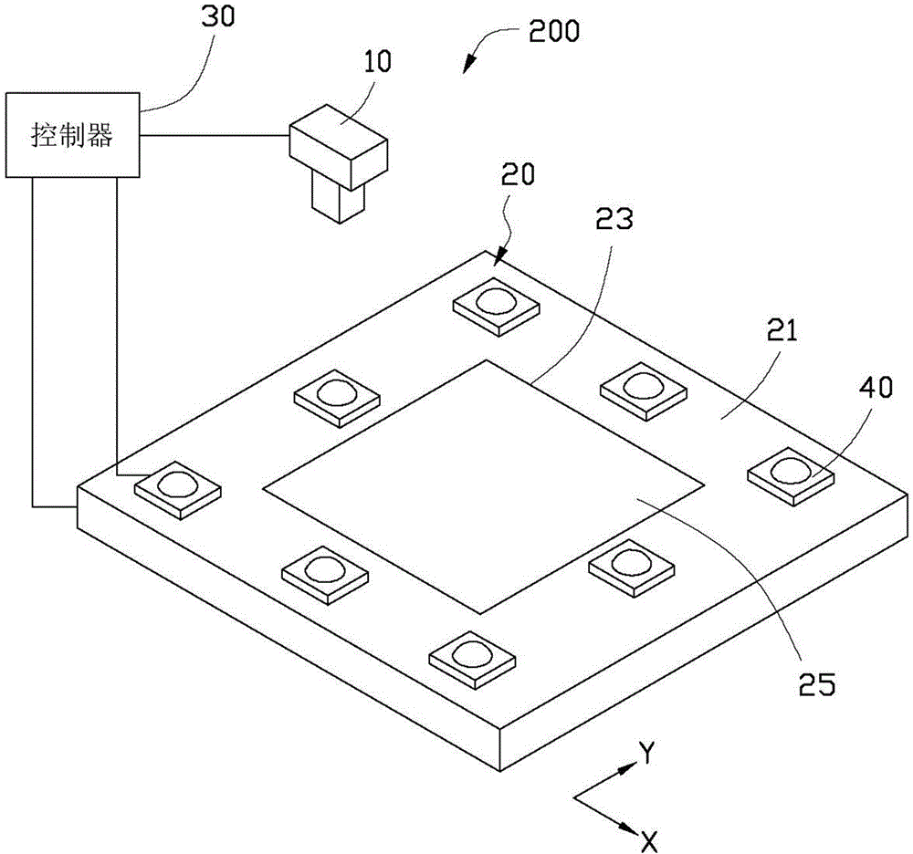
[0021] see figure 1 , figure 2 , which discloses a laser processing machine 200 according to an embodiment of the present invention. The laser processing machine 200 includes a laser head 10 , a carrying unit 20 , a controller 30 , and at least one light sensing unit 40 .

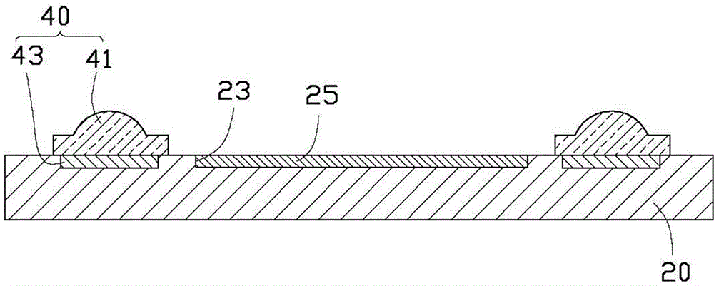
[0022] The bearing unit 20 includes a bearing surface 21, and a bearing hole 23 is formed on the bearing surface 21. In this embodiment, both the bearing surface 21 and the bearing hole 23 are square, and the bearing hole 23 is located at the center of the bearing surface. Location. The carrying hole 23 is used to accommodate and fix a mold core 25 to be processed.

[0023] The laser head 10 is located above the carrying unit 20, the laser head 10 is used to emit laser light, the controller 30 is used to control the laser head 10 to move along a predetermined path, and control the laser head 10 to emit laser light at a predetermined position, thereby Complete dot processing on the die core 25 to be pro...


PUM


Abstract

The invention provides a laser machining machine table. The laser machining machine table comprises a laser head, a bearing unit, a controller and light sensing units. The bearing unit comprises a bearing face, and the laser machining machine table is provided with an origin of coordinates. The light sensing units are fixed to the bearing face. The laser head is used for emitting lasers in multiple different positions. The light sensing units are used for sensing light quantity received in the positions to acquire multiple light quantity values and transmit the light quantity values to the controller. The controller compares the light quantity values and judges the position corresponding to the maximum light quantity value in the light quantity values as the alignment position where the laser head is aligned with the light sensing units, and corrects the position of the origin of the coordinates according to the alignment position. The invention further provides a correction method of the laser machining machine table.

Description

technical field [0001] The invention relates to a laser processing machine and a calibration method thereof. Background technique [0002] The dot structure of the mold core of the light guide plate is generally processed by a laser processing machine. In order to ensure the accuracy of the processing position, it is necessary to correct the processing position of the laser processing machine before processing. The traditional calibration method is to first use laser to mark several dots on a calibration steel plate, then use CCD (charge coupled device) to take pictures to obtain the actual position of the dots on the steel plate, and then compare the actual position of the dots with the predetermined position, so as to obtain position deviation value, and use the position deviation value to correct the position of the laser processing machine. [0003] However, the above-mentioned method of calibrating the laser processing machine needs a calibration steel plate, and the ...

Claims


Application Information

Patent Timeline
IPC IPC(8): B23K26/042
Inventor 黄雍伦
Owner HONG FU JIN PRECISION IND (SHENZHEN) CO LTD
Features
  • R&D
  • Intellectual Property
  • Life Sciences
  • Materials
  • Tech Scout
  • Unparalleled Data Quality
  • Higher Quality Content
  • 60% Fewer Hallucinations
Learn More