Robot automatic welding method for forged hook tail frame

A technology of automatic welding and welding methods, which is applied in the direction of welding medium, welding equipment, welding equipment, etc., can solve the problems of difficult welding root cleaning, unfused weld seams, hidden safety hazards, etc., and achieve saving welding materials and high welding pass rate Improvement, the effect of high welding surface quality

Active Publication Date: 2016-04-27
南京力源轨道交通装备有限公司
View PDF2 Cites 0 Cited by
  • Summary
  • Abstract
  • Description
  • Claims
  • Application Information

AI Technical Summary

Problems solved by technology

With the development of rail transit construction in the direction of high-speed and heavy-duty, the traditional cast steel coupler frame inevitably has defects such as air holes, inclusions, and cracks due to the inherent factors of the casting process, and the existence of these defects poses a threat to the high-speed operation of railway heavy-duty vehicles. Potential safety hazards, and from the statistics of actual operation and maintenance, about 40% of the problems are related to the coupler frame, so it is imminent to improve the manufacturing process of the coupler frame
For this reason, the forging method is generally used to replace the casting process for the coupler frame nowadays. The forged coupler frame is prepared through forging, welding, heat treatment and machining processes, and the welding process is a key process step, which needs to achieve a According to the technical requirements of grade welds, the weld groove is X-shaped groove double-sided welding, because the welding surface is of unequal thickness, so the milled groove is of different width, depth and height; while using robot welding, because it is Double-sided welding forming, the welding root cleaning problem is difficult to solve, resulting in unfused welds and air holes

Method used


Image

  • Robot automatic welding method for forged hook tail frame
  • Robot automatic welding method for forged hook tail frame
  • Robot automatic welding method for forged hook tail frame

Examples


Embodiment 1

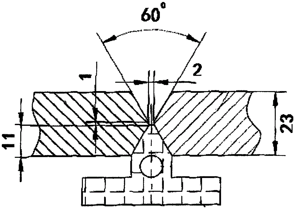
[0020] The forged hook frame is made of E36 steel plate. The parameters of the welded joint are: X-shaped groove, the blunt side of the groove is 2mm, and the groove angle is 60°. Degreasing and cleaning the groove area before welding.

[0021] The welding method includes the following steps: a water-cooled gasket is arranged at the lower end of the X-shaped weld groove, and the water-cooled gasket is flush with the center of the groove and fixed, and then the water-cooled gasket is opened in the water-cooled gasket. Cooling water circulation device; (2) at 90v%Ar+10v%CO 2 In the atmosphere, the welding robot (Panasonic automatic welding machine) is instructed to perform four passes of welding on the upper end of the weld groove. The welding currents of the first to fourth passes are 420A, 420A, 440A and 450A, and the welding voltage They are 28V, 28V, 30V, 30V, and the welding speeds are 48cm / min, 48cm / min, 51cm / min, 52cm / min; (3) Remove the water-cooled gasket and set it at 90v%...

Embodiment 2

[0023] The forged hook frame uses 15MnV steel plate, and the parameters of the welded joint are: X-shaped groove, groove blunt edge is 2mm, groove angle is 60°, and the groove area is degreasing and cleaning before welding.

[0024] The welding method includes the following steps: a water-cooled gasket is arranged at the lower end of the X-shaped weld groove, and the water-cooled gasket is flush with the center of the groove and fixed, and then the water-cooled gasket is opened in the water-cooled gasket. Cooling water circulation device; (2) at 90v%Ar+10v%CO 2 In the atmosphere, the welding robot (Panasonic automatic welding machine) is instructed to perform four passes of welding on the upper end of the weld groove. The welding currents of the first to fourth passes are 420A, 420A, 440A and 450A, and the welding voltage They are 28V, 28V, 30V, 30V, and the welding speeds are 48cm / min, 48cm / min, 51cm / min, 52cm / min; (3) Remove the water-cooled gasket and set it at 90v%Ar+10v%CO 2 ...

Embodiment 3

[0026] The forged hook frame is made of E36 steel plate. The parameters of the welded joint are: X-shaped groove, the blunt side of the groove is 2mm, and the groove angle is 60°. Degreasing and cleaning the groove area before welding.

[0027] The welding method includes the following steps: a water-cooled gasket is arranged at the lower end of the X-shaped weld groove, and the water-cooled gasket is flush with the center of the groove and fixed, and then the water-cooled gasket is opened in the water-cooled gasket. Cooling water circulation device; (2) at 90v%Ar+10v%CO 2 In the atmosphere, the welding robot (Panasonic automatic welding machine) is instructed to perform four passes of welding on the upper end of the weld groove. The welding currents of the first to fourth passes are 420A, 420A, 440A and 450A, and the welding voltage They are 28V, 28V, 30V, 30V, and the welding speeds are 48cm / min, 48cm / min, 51cm / min, 52cm / min; (3) Remove the water-cooled gasket and set it at 90v%...


PUM

PropertyMeasurementUnit
tensile strengthaaaaaaaaaa

Abstract

The invention relates to a method of using a robot for automatic welding of forged coupler yokes. The welding method includes the steps: (1) forming a shape of an X-shaped weld groove, arranging a water cooling pad at the lower end of the X-shaped weld groove after a weld part is fixed, flushing the water cooling pad with the center of the groove, fixing the water cooling pad to the groove, and then starting a cooling water circulation device arranged in the water cooling pad; (2) in a protective atmosphere, instructing a welding robot to perform four-gate welding at the upper end of the weld groove; (3) taking off the water cooling pad, and instructing the welding robot to perform four-gate welding at the lower end of the weld groove in the protective atmosphere. The method of using the robot for automatic welding of the forged coupler yokes has the advantages that labor intensity is remarkably relieved, welding labor hours are reduced, back gouging is not needed, weld testing acceptability is guaranteed, and welding materials are saved.

Description

Technical field [0001] The invention belongs to the technical field of welding technology. More specifically, the invention relates to an automatic welding method for a forging hook and tail frame robot. Background technique [0002] The hook-and-tail frame used on rail transit vehicles is an important part of the coupler's buffer device. When the vehicle is towed, connected and buffered, it directly completes the longitudinal traction or impact force between the vehicles. With the development of rail transit construction in the direction of high speed and heavy load, the traditional cast steel hook and tail frame has unavoidable defects such as pores, inclusions and cracks due to the inherent factors of the casting process, and the existence of these defects constitutes the high-speed operation of railway heavy-load vehicles Potential safety hazards, and from the statistics of actual operation and maintenance, about 40% of the problems are related to the hook frame, so it is imm...

Claims


Application Information

Patent Timeline
Patent Type & Authority Patents(China)
IPC IPC(8): B23K37/00B23K9/16B23K35/30
CPCB23K9/035B23K9/16B23K9/235B23K33/00B23K35/3026B23K35/383B23K37/003
Inventor 扶香荣姬传堂
Owner 南京力源轨道交通装备有限公司
Why Eureka
Try Eureka