Pressing and disassembling device for engine gudgeon pins

A piston pin and engine technology, applied in metal processing, metal processing equipment, manufacturing tools, etc., can solve the problems of low degree of automation, difficult to guarantee assembly accuracy, low assembly efficiency, etc., achieve high degree of mechanical automation, save internal space, Reliable effect

Active Publication Date: 2014-11-19
HEBEI UNIV OF TECH
View PDF9 Cites 5 Cited by
  • Summary
  • Abstract
  • Description
  • Claims
  • Application Information

AI Technical Summary

Problems solved by technology

[0003] At present, the assembly process of the piston, connecting rod and piston pin is usually manual work. The general steps are: first, heat the piston or the small end of the connecting rod, then place the piston on the positioning plate, clean the piston pin hole, and clean the piston pin hole by hand. Push the piston pin into the piston pin hole, then push the small end of the connecting rod deep into the piston, align the piston pin with the pin hole of the small end of the connecting rod, and then hit one end of the piston pin with a wooden hammer to make the piston pin pass through the small end of the connecting rod. The head pin hole reaches the edge of the pin hole at the other end of the piston pin, and then the lock ring is inserted to complete the entire assembly. Since the tools used are scattered, and the small end of the piston or connecting rod needs to be assembled under high temperature, the assembler must move quickly and require With the assistance of multiple people, it is difficult to guarantee the assembly accuracy, the consistency is poor, and the assembly efficiency is low
[0004] Engine piston pin removal tooling (application number 200910207602.3), which discloses a tool that utilizes a jack, a base, a support plate, a guide rod and a guide rod seat to realize the removal of the engine piston pin, and it supports the piston connecting rod assembly by the guide rod seat, Insert the guide rod in the guide rod seat into the piston and contact the end face of the piston pin, and operate the jack to move the guide rod seat upwards. At this time, the jack rod will push the piston pin down and drive the guide rod into the guide hole until the piston The pin is pushed out of the piston. In the described embodiment, a jack is used to disassemble the piston pin, which has a low degree of automation and low efficiency and cannot meet the production requirements of the production line; the invention patent is based on an industrial robot-based piston, piston pin and connecting rod assembly method and dev

Method used


Image

  • Pressing and disassembling device for engine gudgeon pins
  • Pressing and disassembling device for engine gudgeon pins
  • Pressing and disassembling device for engine gudgeon pins

Examples


Embodiment Construction

[0032] The present invention is further described below in conjunction with embodiment and accompanying drawing.

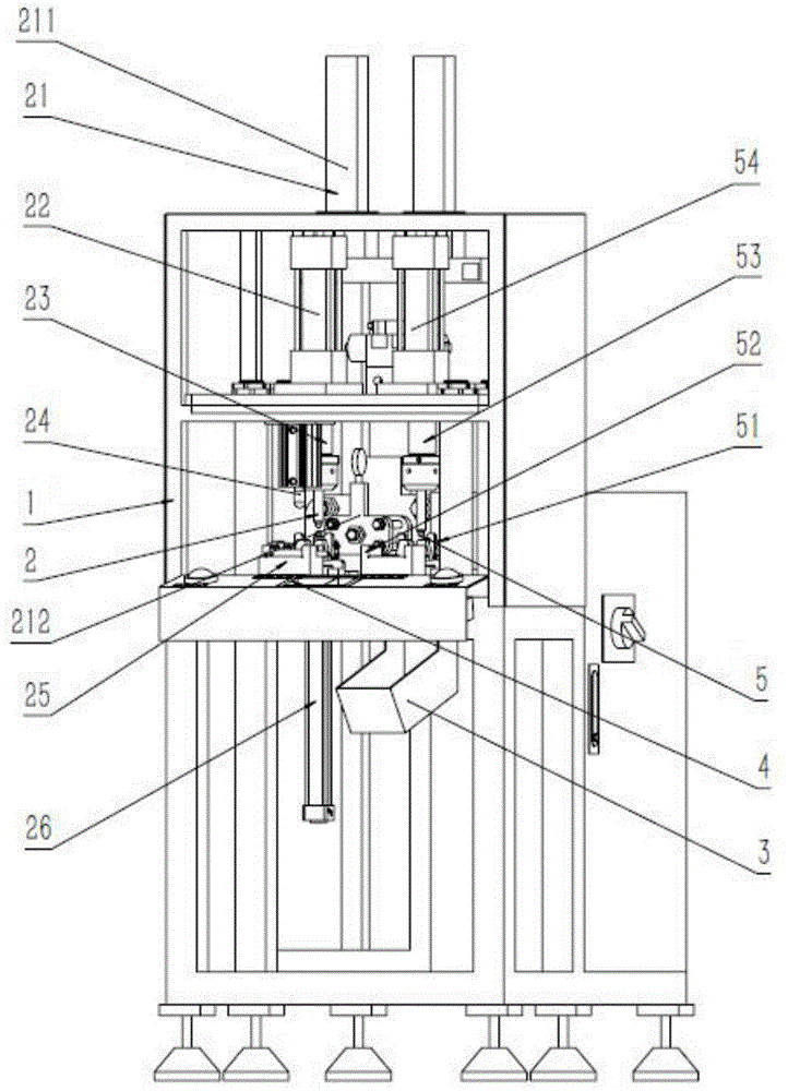
[0033] What the present invention designs is a kind of press dismantling device of engine piston pin (abbreviation device, refer to figure 1 , 4 -6, 8-17), including the pin drop groove 3 and the connecting pin oil immersion groove assembly 4, characterized in that the device also includes a support frame assembly 1, a pin pressing mechanism 2 and a pin removal mechanism 5.

[0034] The support frame assembly 1 (see figure 1 , 16 , 17) consists of skeleton structure 11, control cabinet 12, rear lower fixed plate 13, rear upper fixed plate 14, front upper fixed plate 15, support column 16, button bracket 17, two-hand operation button 18, front lower fixed plate 19 and can adjustable feet 110; the lower part of the frame structure 11 is screwed to fix the adjustable feet 110; the control cabinet 12 is fixed to the rear of the frame structure 11 by bolts; both end...


PUM

PropertyMeasurementUnit
Rotation angleaaaaaaaaaa

Abstract

The invention discloses a pressing and disassembling device for engine gudgeon pins. The device comprises a pin falling tank and a connecting pin oil immersion tank component. The device is characterized by further comprising a support frame component, a pin pressing mechanism and a pin disassembling mechanism. By the device, assembling of piston and connecting rod assemblies can be completed efficiently, and the piston and connecting rod assemblies unqualified in assembling can be disassembled in time; in addition, type stoppers of the piston and connecting rod assemblies are added to the device, assembling and disassembling of the piston and connecting rod assemblies of two different types can be completed, and the device has the advantages of high mechanical automation, high safety and the like; meanwhile, compared with the prior art, the pressing and disassembling device is simple in structure, convenient to operate and high in reliability.

Description

technical field [0001] The invention belongs to the technical field of production of engine connecting rod pistons, and in particular relates to a pressing and dismantling device for engine piston pins. Background technique [0002] The piston connecting rod assembly is the central part of the engine, and its assembly quality has a direct impact on the sealing and service life of the cylinder. The piston connecting rod assembly is generally composed of piston, piston pin and connecting rod. The connecting rod is composed of connecting rod body, connecting rod cover, connecting rod bolt and connecting rod bearing bush. The connecting rod body is divided into connecting rod small head, shaft and The big end of the connecting rod and the small end of the connecting rod are used to install the piston pin. The piston uses the piston pin to make the connecting rod drive the crankshaft to rotate, thereby converting the linear reciprocating motion of the piston into the rotary motio...

Claims


Application Information

Patent Timeline
IPC IPC(8): B23P19/027
CPCB23P19/027
Inventor 曹国忠魏丛格郭海霞穆秀秀刘伟
Owner HEBEI UNIV OF TECH
Why Eureka
Try Eureka