Reinforced concrete stop log gate sealing method

A technology of reinforced concrete and stacked beam gates, which is applied in water conservancy projects, sea area projects, coastline protection, etc. It can solve the problems of large water leakage, incomplete joint joints, and high investment in steel gates, so as to improve water leakage problems and better blockage effect, the effect of low material cost

Inactive Publication Date: 2014-11-19
ANHUI WATER RESOURCES DEV
View PDF4 Cites 6 Cited by
  • Summary
  • Abstract
  • Description
  • Claims
  • Application Information

AI Technical Summary

Problems solved by technology

However, when concrete stacking beams are used, it is generally necessary to stack several or dozens of concrete stacking beams together to meet the water-retaining requirements, because the absolute flatness and smoothness of the surface of the stacking beams cannot be guaranteed after prefabrication, resulting in stacking During the beam installation process, the joints between the upper and lower beams cannot be completely matched, and the joints between the stacked beam and the gate groove structure are not tight. The construction of the diversion tunnel plugging section and the later operation of the project have a great impact
It is difficult to prevent it from becoming a channel for water seepage when simply using rubber belts or cotton wool to block it. The more the number of stacking beams, the more gaps there will be, so the water seepage will increase, making the construction of the diversion hole plug body difficult or even impossible. Construction; when steel gates are used to retain water, although the steel gates have a good water retaining effect, the investment of steel gates is relatively high, and the steel gates cannot be recycled and reused after the gates are closed, so the project investment is relatively increased
Therefore, the existing gate structure for the lower gate of the diversion tunnel is still not ideal.

Method used


Image

  • Reinforced concrete stop log gate sealing method
  • Reinforced concrete stop log gate sealing method
  • Reinforced concrete stop log gate sealing method

Examples


Embodiment Construction

[0018] The preferred embodiments of the present invention will be described in detail below in conjunction with the accompanying drawings, so that the advantages and features of the present invention can be more easily understood by those skilled in the art, so as to define the protection scope of the present invention more clearly.

[0019] A water-stopping method for a reinforced concrete stacked beam gate, comprising the following steps:

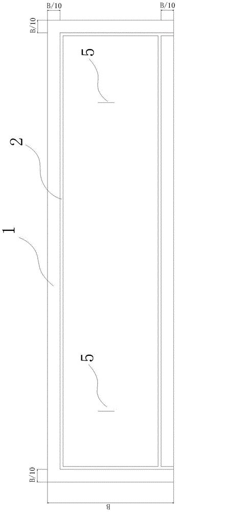
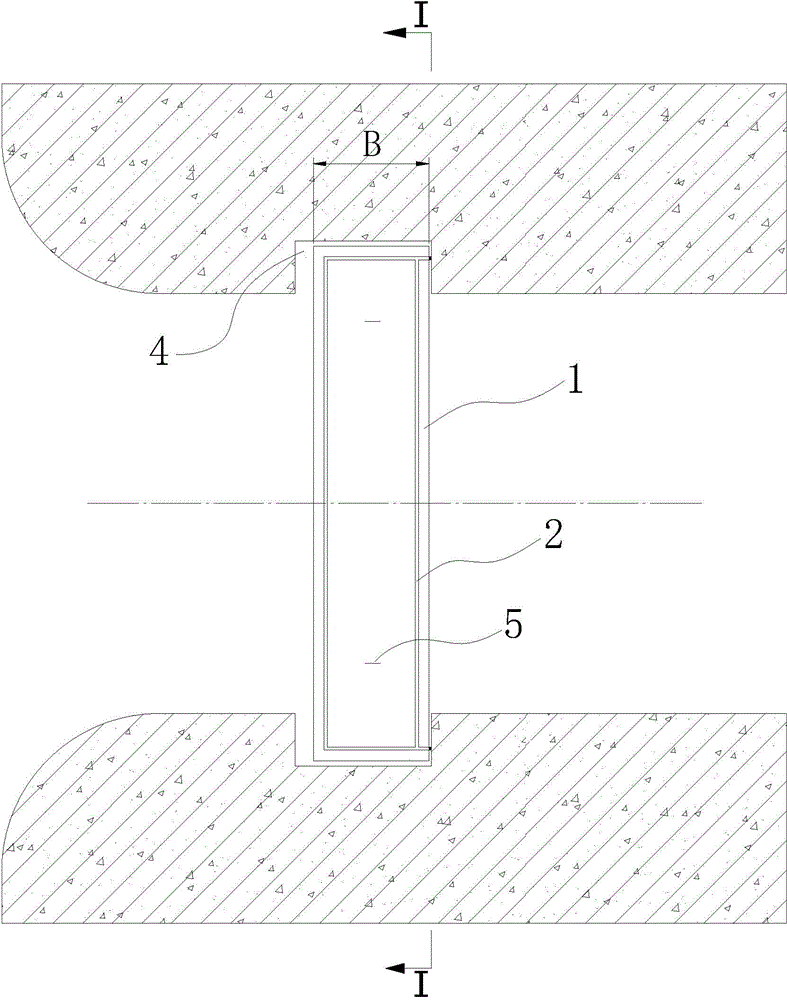
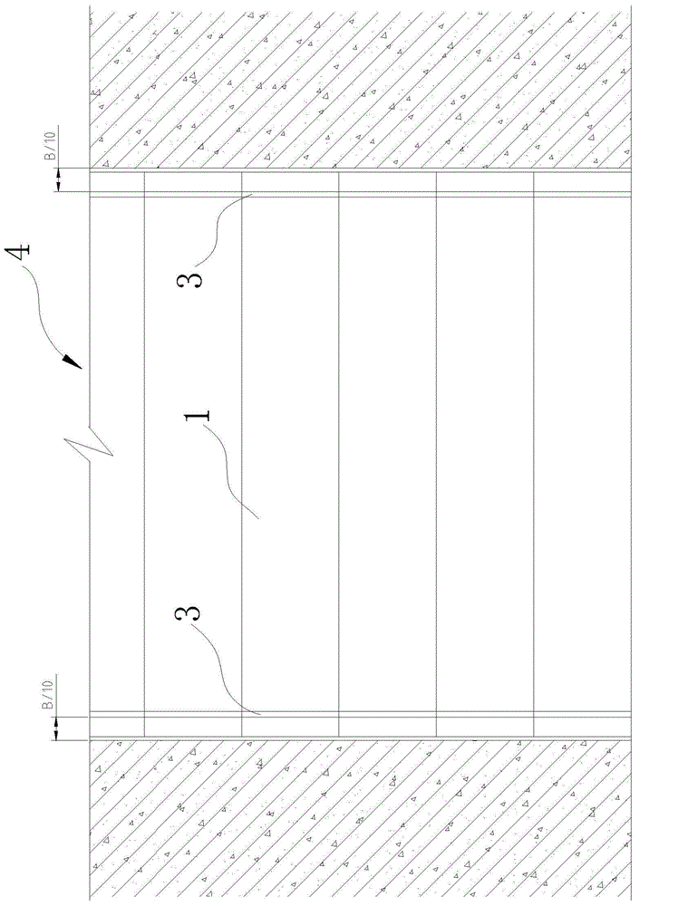
[0020] Step 1: Clean the surface of the stacking beam 1, and attach rubber water-stop strips to the surface of the stacking beam 1 at a distance of B / 10 from the surrounding edges (set the width of the stacking beam as B), so as to form a closed circle of horizontal water-stop strips 2;

[0021] First, clean the outer surface of the stacking beam 1, and trim the pockmarked or uneven parts to make them clean and free of debris. In a preferred embodiment, the rubber water-stop strip adopts a regular rubber water-stop strip with a specificat...


PUM


Abstract

The invention discloses a reinforced concrete stop log gate sealing method. The method comprises the following steps that firstly, the surfaces of stop logs are cleaned, rubber sealing strips are pasted at the position, away B / 10 (the width of the stop logs is B) from the peripheral edges, of the surfaces of the stop logs, and therefore a circle of sealed horizontal sealing strips is formed by the rubber sealing strips; secondly, rubber sealing strips are pasted at the positions, away B / 10 from the side walls of gate grooves, of the inner surfaces of the gate grooves, and perpendicular sealing strips is formed by the rubber sealing strips; thirdly, the stop logs in the first step are sequentially lifted and placed in the gate grooves, and the horizontal sealing strips and the perpendicular sealing strips exposed out of the gate grooves are firmly pasted; fourthly, the above steps are repeated until the last stop log is lifted, and finally concrete is used for integrally casting and covering the stop logs. The method is simple, convenient to construct and low in material cost, a plastic colloidal system is formed between the stop logs, and after the stop logs are blocked, the water leakage problem is solved.

Description

technical field [0001] The invention relates to the technical field of water conservancy and hydropower engineering, in particular to a water-stopping method for a reinforced concrete stacked beam gate. Background technique [0002] In the construction of domestic hydropower projects, when the water retaining head of the gate used for the lower gate of the diversion tunnel is low or the end face size of the diversion tunnel is small, the entrance of the diversion tunnel is generally closed by using a concrete stacked beam steel gate to lower the diversion tunnel. Purpose. However, when concrete stacking beams are used, it is generally necessary to stack several or dozens of concrete stacking beams together to meet the water-retaining requirements, because the absolute flatness and smoothness of the surface of the stacking beams cannot be guaranteed after prefabrication, resulting in stacking During the beam installation process, the joints between the upper and lower beams ...

Claims


Application Information

Patent Timeline
Patent Type & Authority Applications(China)
IPC IPC(8): E02B7/22E02B7/54
Inventor 张秀军郑碧水朱胜汝邵毅李超雷祥全张翔裴看元
Owner ANHUI WATER RESOURCES DEV
Why Eureka
Try Eureka