Loader bucket

A loader and bucket technology, applied in the field of buckets, can solve the problems of large shovel entry resistance and low shovel loading efficiency, and achieve the effects of increasing bucket capacity, improving shovel loading efficiency, and improving connection reliability.

Active Publication Date: 2014-11-19
GUANGXI LIUGONG MASCH CO LTD
View PDF5 Cites 2 Cited by
  • Summary
  • Abstract
  • Description
  • Claims
  • Application Information

AI Technical Summary

Problems solved by technology

[0004] The purpose of the present invention is to provide a loader bucket, which can solve the problems of high shoveling resistance and low shoveling efficiency before the crushing of cold steel slag

Method used


Image

  • Loader bucket
  • Loader bucket
  • Loader bucket

Examples


Embodiment 1

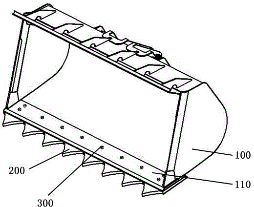
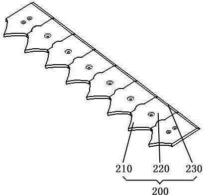
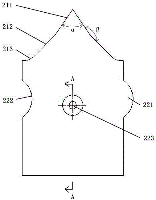
[0032] figure 1 The loader bucket shown includes a bucket body 100 and a plurality of bucket teeth installed at the front end of the bucket body 100, and these bucket teeth are a plurality of movable blades 200 spliced ​​side by side, see figure 2 The movable blade 200 is a flat plate, and each movable blade 200 is installed and fixed under the main cutting plate 110 of the bucket body 100 by means of bolt connection. After the installation is completed, the working part of the movable blade 200 protrudes from the main Cutting the outside edge of plate 110; as image 3 The movable knife plate 200 shown has a connecting part 220 and two working parts respectively arranged at the two ends of the connecting part 220. The two working parts are the tine part 210 and the flat tooth part 230 connected with the connecting part 220 respectively. The free end of the tooth part 210 is a pointed tooth tip, which extends obliquely from the tooth tip to the two sides of the connecting par...

Embodiment 2

[0035] Such as Figure 7 and Figure 8 As shown, the structural features of the bucket body 400, the main cutting plate 410 and the movable knife plate 500 of this embodiment are the same as those of the first embodiment, the difference is that the two outermost movable knife plates 500 are turned backward by 180° during installation. °, the installation positions are exchanged with each other, and the rest of the movable blades 500 only need to move backward 180°, that is, press each movable blade 500 Figure 8 The splicing method is installed and fixed under the main cutting plate 410 of the bucket body 400, so that the flat teeth 510 of each movable knife plate 500 protrude from the outside of the main cutting plate 410. After the installation is completed, it can be used for shoveling and crushing treatment. The cold steel slag, which is a loose material with low density, is closely connected with the flat teeth 510 of the adjacent movable blades 500 during the shoveling ...

Embodiment 3

[0037] In this embodiment, the included angle α between the two sections of the first beveled edge of the tine portion of the movable blade is 75°, and the included angle β between the first beveled edge and the second beveled edge on the same side is 150°. All the other features are the same as in Example 1.


PUM


Abstract

The invention discloses a loader bucket, and relates to the technical field of loader buckets. The loader bucket comprises a loader bucket body and a plurality of bucket teeth installed at the front end of the bucket body. The bucket teeth are a plurality of movable knife plates spliced side by side, and the movable knife plates are connected with the bucket body through fasteners. Each movable knife plate is provided with a connection portion, and one or more sharp tooth portions arranged at one end of the corresponding connection portion and connected with the corresponding connection portion into a whole. The free end of each sharp tooth portion is a sharp-corner-shaped tooth top, and each sharp tooth portion extends obliquely towards the two sides of the corresponding connection portion from the tooth top to form two first oblique edges. Compared with the prior art, due to the fact that the work portions of the movable knife plates can be adjusted, the loader bucket has dual effects, thereby being capable of better adapting to the working conditions of shoveling and loading cold steel slag and greatly improving the working efficiency.

Description

technical field [0001] The invention relates to the technical field of buckets, in particular to a loader bucket used for shoveling cold steel slag. Background technique [0002] In the iron and steel manufacturing industry, a large amount of slag is produced in the process of iron and steel smelting. The cold steel slag formed after the slag is cooled needs further treatment such as shoveling and crushing. The treated steel slag can be used for paving roads and building materials. As a highly efficient operating equipment, wheel loaders are increasingly used in the processing of cold steel slag. [0003] The steel slag after being released from the furnace is cooled by water and air to form cold steel slag. Cold steel slag is a kind of agglomerated object with high hardness, high brittleness and a large number of pores. The existing loader bucket includes a bucket body and a plurality of bucket teeth installed at the front end of the bucket body. There is a certain distan...

Claims


Application Information

Patent Timeline
Patent Type & Authority Applications(China)
IPC IPC(8): E02F9/28
Inventor 梁光明古灿民
Owner GUANGXI LIUGONG MASCH CO LTD
Why Eureka
Try Eureka