
Chain type cutter assembly structure

A cutter and assembly technology, applied in the direction of shaft lining, tunnel lining, underground chamber, etc., can solve the problems of inconvenience, extension of construction period, soil stress release, etc., to facilitate installation and disassembly, improve grouting efficiency, good looking effect

Active Publication Date: 2014-11-19
CHINA RAILWAY CONSTR HEAVY IND
View PDF5 Cites 6 Cited by
  • Summary
  • Abstract
  • Description
  • Claims
  • Application Information

AI Technical Summary

Problems solved by technology

[0004] The chain saw type grooving head is its key component in the pre-grooving machine, but the existing research shows that the existing chain saw type grooving head has the following defects: (1) the chain saw type grooving head only has cutting Due to the function of the soil, it is impossible to complete the concrete grouting work after grooving. Other equipment is required to grout after grooving. There is a time separation between grooving and grouting, which is prone to soil stress release and even collapse. (2) The grouting process requires additional equipment for construction, which increases the construction burden and inconvenience of operation, and also greatly prolongs the construction period

Method used


Image

  • Chain type cutter assembly structure
  • Chain type cutter assembly structure
  • Chain type cutter assembly structure

Examples


Embodiment 1

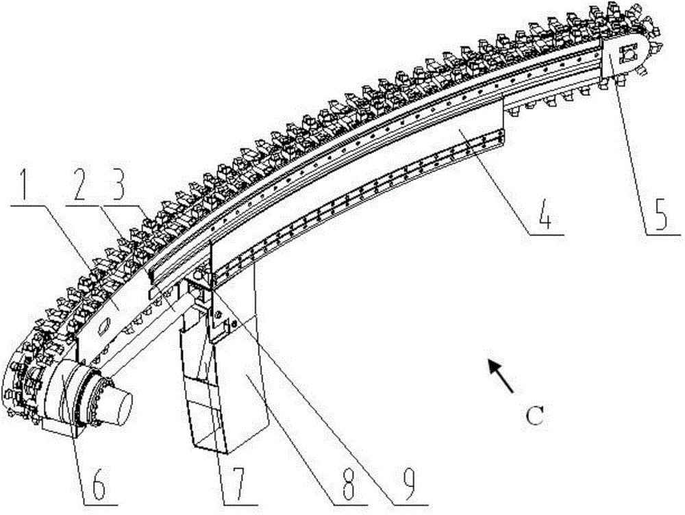
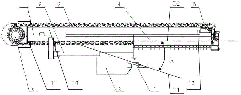
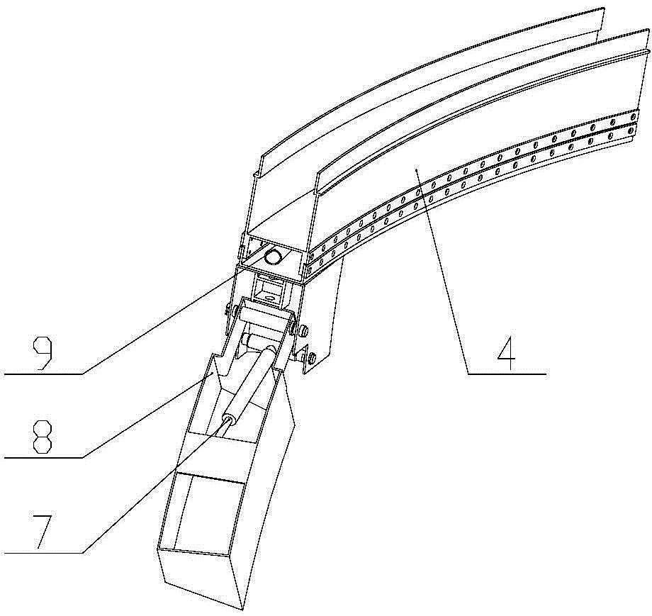
[0035] A chain cutter assembly mechanism, see figure 1 , figure 2 as well as image 3 , including cutter body 1, sliding form telescopic cylinder 2, chain cutter 3, sliding template 4, driven device 5, driving device 6, vertical mold opening and closing cylinder 7, vertical template 8 and grouting pipe 9, wherein cutter body 1 , chain knife 3, driven device 5 and driving device 6 are combined to form a grooving mechanism, sliding form telescopic cylinder 2, sliding formwork 4, vertical mold opening and closing cylinder 7, vertical formwork 8 and grouting pipe 9 are combined to form a concrete synchronous pouring mechanism , The concrete synchronous pouring mechanism is fixed on the grooving mechanism, which acts synchronously with the grooving mechanism, and the overall structure is simplified.

[0036] The cutter body 1 includes a front end 11, an end 12 and a side surface 13, and the driving device 6 and the driven device 5 are movably arranged on the end 12 and the front...


PUM


Abstract

The invention provides a chain type cutter assembly structure comprising a cutter body, a sliding formwork telescopic cylinder, a chain cutter, a sliding form, a drive device, an erecting formwork opening and closing cylinder, an erecting form and a grouting pipe. The drive device is movably arranged on the cutter body. The chain cutter is assembled on the cutter body and meshed with the drive device. The sliding form is movably connected with the cutter body. The tail end of the sliding formwork telescopic cylinder is movably connected with the cutter body, and the front end of the sliding formwork telescopic cylinder is movably arranged on the sliding form. The grouting pipe is arranged on the sliding form which is provided with a grout outlet communicated with the grouting pipe. The upper end of the erecting form is movably arranged on the sliding form. Two ends of the erecting formwork opening and closing cylinder are arranged on the sliding form and the erecting form respectively. The chain type cutter assembly structure is simple in the whole structure; the cutter body, the chain cutter, the drive device and a driven device form a grooving mechanism to drive the chain cutter to move, so that feed cutting and annular cutting are achieved; the sliding form, the erecting form, the erecting formwork opening and closing cylinder and the grouting pipe form a concrete synchronous grouting mechanism to do synchronous motion with the grooving mechanism, thus synchronous grouting is achieved.

Description

technical field [0001] The invention relates to the field of tunnel construction machinery equipment, in particular to a chain cutter assembly mechanism. Background technique [0002] In the drilling and blasting construction of tunnels in my country, the tunnel construction technology in weak surrounding rock is a weak link compared with hard rock. The main performance is that there are not many effective anti-collapse methods and the equipment is not matched. In this case, pre-support technology is required. , The pre-cut groove method can be used for full-section or half-section construction, which can greatly improve the mechanization level of construction, and can effectively control problems such as surface settlement. [0003] In the 1990s, our country began to study pre-grooving equipment and completed the chain saw type working head of pre-grooving machine and its testing machine, but it did not carry out engineering practical application. [0004] The chain saw typ...

Claims


Application Information

Patent Timeline
IPC IPC(8): E21D9/10E21D11/10
Inventor 刘飞香王守慧郑大桥田泽宇陈力邹海炎
Owner CHINA RAILWAY CONSTR HEAVY IND
Learn More