

Method for autonomous measurement of pose of tripod structure of solar panel on non-cooperative spacecraft
A technology for solar panels and spacecraft, which is applied in measurement devices, integrated navigators, photogrammetry/video surveying, etc. Avoid the effect of delay and system instability
- Summary
- Abstract
- Description
- Claims
- Application Information
AI Technical Summary
Problems solved by technology
Method used
Image

Examples
Embodiment Construction
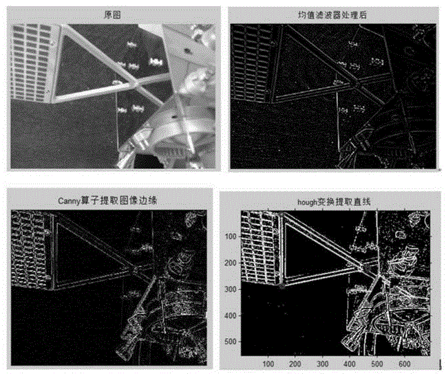
[0019] A method for autonomous measurement of the position and orientation of a tripod structure with solar panels on a non-cooperative spacecraft, image processing steps:
[0020] (1) Use the Canny operator to extract the edge of the image: use a Gaussian filter to smooth the image, then use the finite difference of the first-order partial derivative to calculate the magnitude and direction of the gradient, then suppress the gradient magnitude by non-maximum value, and finally use Double-threshold algorithm detects and connects edges;
[0021] (2) Carry out mean value filter, reduce the noise of pixel;
[0022] (3) Image binarization: that is, grayscale division, which refers to setting a grayscale value. If the grayscale of the image itself is greater than it, it will be a bright spot, and if the grayscale value is lower than the set value, it will be a bright spot. scotoma, thus obtaining a binary image.
[0023] A method for autonomous measurement of the position and ori...
PUM
 Abstract
Description
Claims
Application Information