Installation method of optical fiber acceleration sensor for turbine generator stator end vibration measurement

A technology of acceleration sensors and turbogenerators, applied in measuring devices, instruments, and using wave/particle radiation, etc., can solve the problems of non-detachable, waste of resources, and damage to the insulation layer of the measured parts, so as to ensure authenticity and reliability Sexuality, easy installation and disassembly, and high-risk effects

Inactive Publication Date: 2014-11-19
HARBIN ELECTRIC MASCH CO LTD
View PDF5 Cites 3 Cited by
  • Summary
  • Abstract
  • Description
  • Claims
  • Application Information

AI Technical Summary

Problems solved by technology

[0002] Since the generator stator winding is a charged body under a strong electromagnetic field, environmental factors such as high temperature, strong magnetic field, high voltage, etc. will generate strong interference. The traditional test method using piezoelectric sensors is limited and there are certain safety hazards. At the same time, it will introduce interference signals and cannot accurately measure the real value
At present, fiber optic acceleration sensors are mostly used for vibration testing of the end windings of turbogenerators, but the sensor installation methods used are non-removable, the sensors cannot be reused, and cannot be removed when they are installed on the tested parts, otherwise they will be damaged. Destruction of the insulation of the component under test
This method not only brings huge waste of resources, but also brings certain safety hazards to the operation of the unit due to the non-detachable nature of the sensor.

Method used


Image

  • Installation method of optical fiber acceleration sensor for turbine generator stator end vibration measurement

Examples


Embodiment Construction

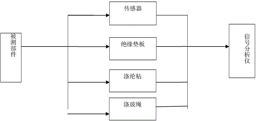
[0016] Such as figure 1 As shown, a method for installing an optical fiber acceleration sensor for vibration measurement at the end of a turbogenerator stator, the method includes the following steps:

[0017] Step 1: First select a suitable location for the component under test, usually in a location with relatively large vibration and easy sensor installation, and clean the surface of the component under test to facilitate the installation of the sensor.

[0018] Step 2: Cut the appropriate insulating backing plate according to the position requirements of the measured part. The thickness of the insulating backing plate is 2.0mm. The insulating backing plate is used here to protect the sensor. After the experiment, just remove the insulating backing plate from the As the optical fiber acceleration sensor is easily damaged, this method not only protects the sensor, but also protects the insulation layer of the measured part, and improves the installation and removal efficienc...


PUM


Abstract

The invention relates to an installation method of an optical fiber acceleration sensor for turbine generator stator end vibration measurement. The method comprises the steps that the optical fiber acceleration sensor is preinstalled on an insulating padding plate through an instant adhesive, the insulating padding plate is a glass plate with the thickness being 2.0 mm, the insulating padding plate is installed on a component to be measured through a small quantity of instant adhesive, the outer side of the optical fiber acceleration sensor is bound by polyester viscose with the thickness being 0.8 mm, the outer side of the polyester viscose is bound by two circles in the mode that a polyester glass rope is soaked in an epoxy resin adhesive, and curing needs to be carried out for more than 12 hours after binding is finished. According to the installation method, the problem that a sensor for turbine generator stator end vibration measurement is hard to assemble or disassemble is solved, the experiment proves that the insulating padding plate with the thickness being 2.0 mm has the 0.2-0.4%. influence on data, and the influence is within the error allowance range. Meanwhile, the sensor for vibration measurement can be repeatedly used, so that the cost is saved.

Description

technical field [0001] The invention relates to an installation method of an optical fiber acceleration sensor used for vibration measurement at the stator end of a steam turbine generator. Background technique [0002] Since the generator stator winding is a charged body under a strong electromagnetic field, environmental factors such as high temperature, strong magnetic field, high voltage, etc. will generate strong interference. The traditional test method using piezoelectric sensors is limited and there are certain safety hazards. At the same time, interference signals will be introduced and the real value cannot be accurately measured. At present, fiber optic acceleration sensors are mostly used for vibration testing of the end windings of turbogenerators, but the sensor installation methods used are non-removable, the sensors cannot be reused, and cannot be removed when they are installed on the tested parts, otherwise they will be damaged. Destruction of the insulati...

Claims


Application Information

Patent Timeline
Patent Type & Authority Applications(China)
IPC IPC(8): G01H9/00
Inventor 陈光辉吴和静钟苏王燕李建伟
Owner HARBIN ELECTRIC MASCH CO LTD
Why Eureka
Try Eureka