Humidity-controllable static gas-sensitive test device and method

A test device, static technology, applied in the direction of measuring device, humidity control, non-electric variable control, etc., can solve the problems of poor stability, poor humidity controllability, difficult to build, etc., to achieve low cost, simple device, simple and stable Effect

Inactive Publication Date: 2014-11-19
HEILONGJIANG UNIV
View PDF2 Cites 10 Cited by
  • Summary
  • Abstract
  • Description
  • Claims
  • Application Information

AI Technical Summary

Problems solved by technology

[0008] The purpose of the present invention is to solve the problems of poor humidity controllability, difficulty in building and poor stability of existing gas-sensing testing devices and methods. The invention provides a static gas-sensing testing device and method with controllable humidity

Method used


Image

  • Humidity-controllable static gas-sensitive test device and method
  • Humidity-controllable static gas-sensitive test device and method
  • Humidity-controllable static gas-sensitive test device and method

Examples


specific Embodiment approach 1

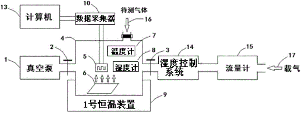
[0035] Specific implementation mode one: see figure 1 Describe this embodiment mode, a kind of controllable humidity static gas sensitive testing device described in this embodiment mode, it comprises gas test system, humidity control system 14 and data acquisition system,

[0036] The gas testing system includes a gas chamber 4, a gas sensor 5, a fan 6, a thermometer 7, a hygrometer 8 and No. 1 thermostatic device 9;

[0037] The data acquisition system includes a data collector 10 and a computer 13;

[0038] The air inlet of the humidity control system 14 is used to pass into the carrier gas 17, the air outlet of the humidity control system 14 communicates with the No. 1 air inlet of the air chamber 4 through the No. 1 gas valve 3, and the air chamber 4 is provided with Gas sensor 5, fan 6, thermometer 7 and hygrometer 8; fan 6 is used to mix the gas to be measured in the gas chamber 4,

[0039] The signal output end of gas sensor 5 is connected with the data signal input ...

specific Embodiment approach 2

[0043] Embodiment 2: The difference between this embodiment and the humidity-controllable static gas-sensing test device described in Embodiment 1 is that it also includes a vacuum pump 1, and the vacuum pump 1 communicates with the gas chamber 4 through the No. 2 gas valve 2 .

specific Embodiment approach 3

[0044] Specific embodiment three: the difference between this embodiment and the static gas-sensing test device with controllable humidity described in specific embodiment one or two is that it also includes a flow meter 15, and the flow meter 15 is used to measure the load Gas 17 flow.

[0045] In this embodiment, the flow meter 15 and the vacuum pump 1 constitute a gas flow system for adjusting the flow and velocity of the carrier gas 17 .


PUM


Abstract

The invention discloses a humidity-controllable static gas-sensitive test device and method, relates to a gas-sensitive test device and method, and aims to solve the problems of bad humidity controllability, difficult construction, and bad stability in the conventional gas-sensitive test devices and methods. The device comprises a humidity control system, the humidity control system is provided with a gas inlet, which is used to introduce carrier gas, the outlet of the humidity control system is communicated to No.1 gas inlet of a gas chamber through a No.1 gas valve, a gas-sensitive element, a fan, a thermometer and hygrometer are arranged in the gas chamber, the fan is used to mix the gas in the gas chamber, the signal output terminal of the gas-sensitive element is connected to the digital signal input terminal of a data collector, the digital signal output terminal of the data collector is connected to the digital signal input terminal of a computer, a No.1 temperature constant device is used to control the temperate of the gas chamber, and the gas chamber is provided with a No.2 gas inlet, which is used to introduce a gas sample to be tested. The device and method are mainly used to carry out gas-sensitivity tests on inorganic gas.

Description

technical field [0001] The invention relates to a gas sensitive testing device and a measuring method. Background technique [0002] At present, with the continuous deepening of research on the gas-sensing properties of materials, people's requirements for gas-sensing testing devices are becoming higher and higher. There are many types of gas-sensing testing devices, which can be divided into two categories: dynamic gas-sensing testing devices and static testing devices. Gas sensitivity testing device. [0003] The dynamic gas sensing test device generally adjusts the flow rate of the measured gas and the carrier gas through a mass flow controller (MFC), mixes the two to obtain the required concentration of the test gas, and then makes the gas continuously pass through the gas sensor containing the gas sensor. The container, use the data collector to collect data and complete data recording and processing by computer, and finally complete the gas sensitivity test (Zuquan Wu...

Claims


Application Information

Patent Timeline
Patent Type & Authority Applications(China)
IPC IPC(8): G01N33/00G05D22/02
Inventor 陈志敏吴昊梁秀华郭良宵王彬贺春英吴谊群
Owner HEILONGJIANG UNIV
Why Eureka
Try Eureka