A stepping aperture device with a photoelectric detection device

A technology of photoelectric detection and aperture, which is applied in aperture, optics, cameras, etc., can solve the problems that the aperture cannot be controlled with high precision, unfavorable precise adjustment of the size of the aperture, and low transmission precision of the transmission mechanism, and achieves simple structure, adjustment and control The effect of high precision and increased transmission ratio

Active Publication Date: 2016-08-17
UNION OPTECH
View PDF7 Cites 1 Cited by
  • Summary
  • Abstract
  • Description
  • Claims
  • Application Information

AI Technical Summary

Problems solved by technology

However, the aperture device controlled by the stepping motor also has its own disadvantages: the aperture is positioned by the mechanical limit structure when it is completely closed, and the mechanical structure of the plastic product is easily deformed by force, and the precise control of the aperture cannot be completed when it is reset to zero. The adjustment of the aperture size is adjusted based on the zero point, so when the fully closed position of the aperture (zero point) cannot be accurately controlled, the aperture size adjustment will not be able to complete high-precision control; in addition, the traditional aperture drive device is Set the dial on the turntable, the driving gear meshes with the dial, and the driving gear rotates to turn the turntable. Such a transmission mechanism has low transmission accuracy and is not conducive to the precise adjustment of the aperture size.

Method used


Image

  • A stepping aperture device with a photoelectric detection device
  • A stepping aperture device with a photoelectric detection device
  • A stepping aperture device with a photoelectric detection device

Examples


Embodiment Construction

[0026] The present invention will be further described below in conjunction with accompanying drawing:

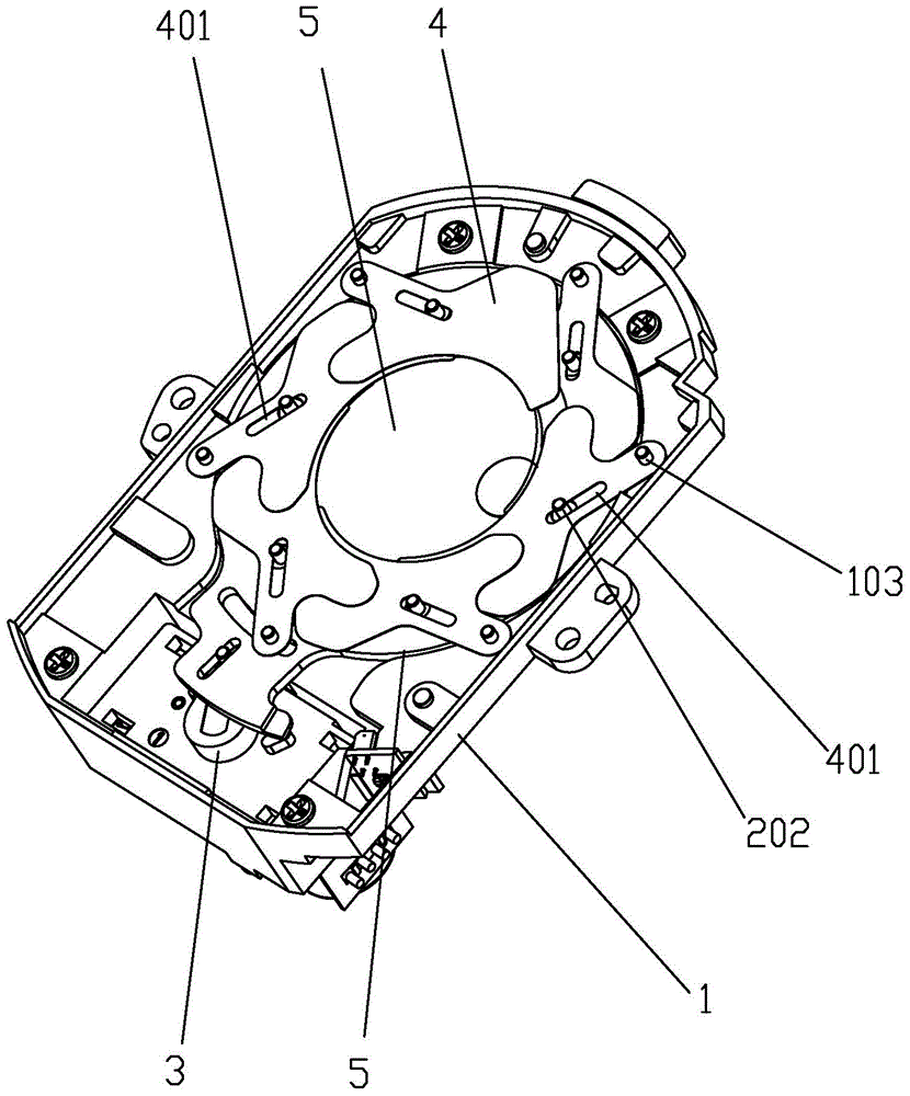
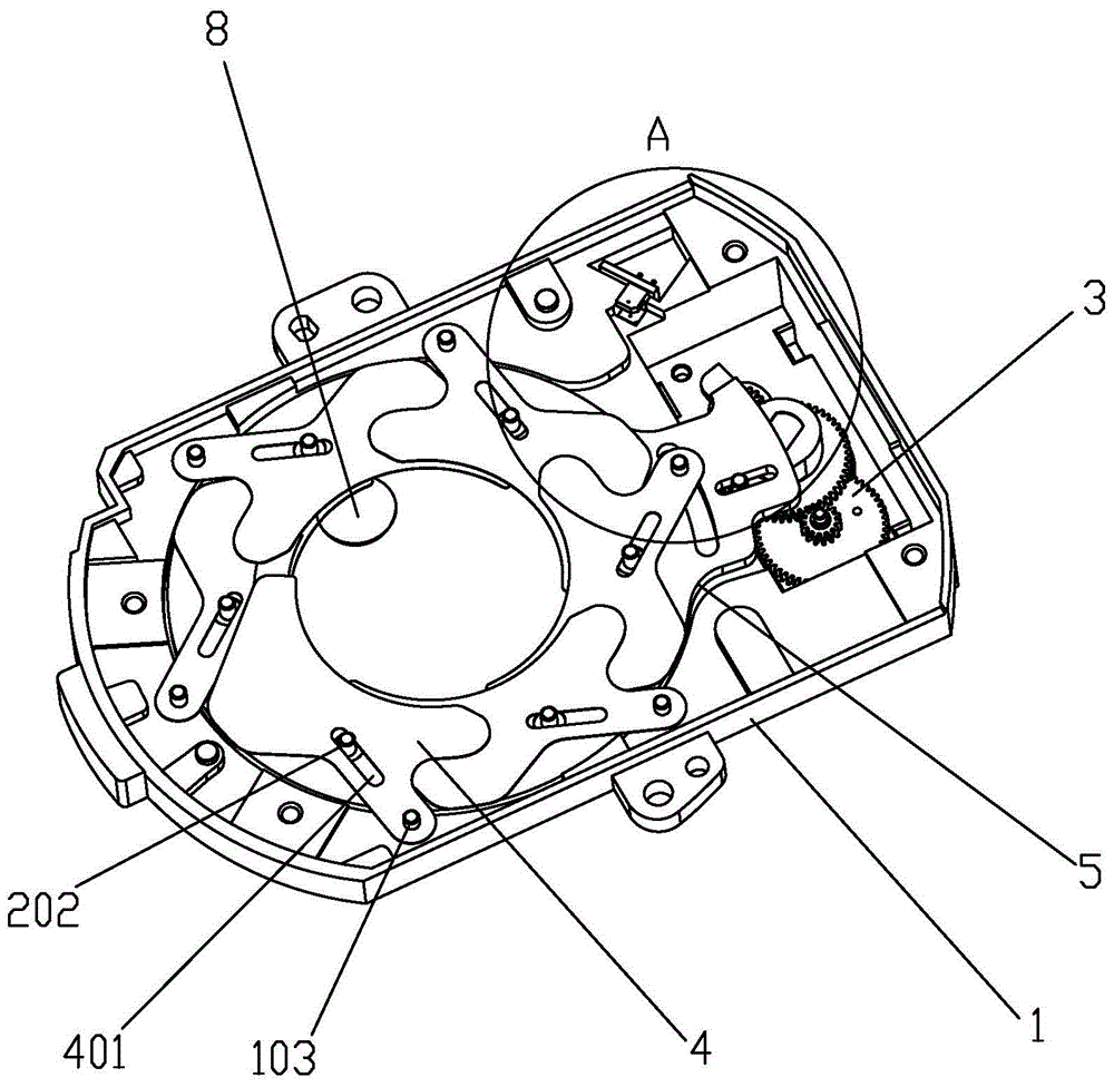
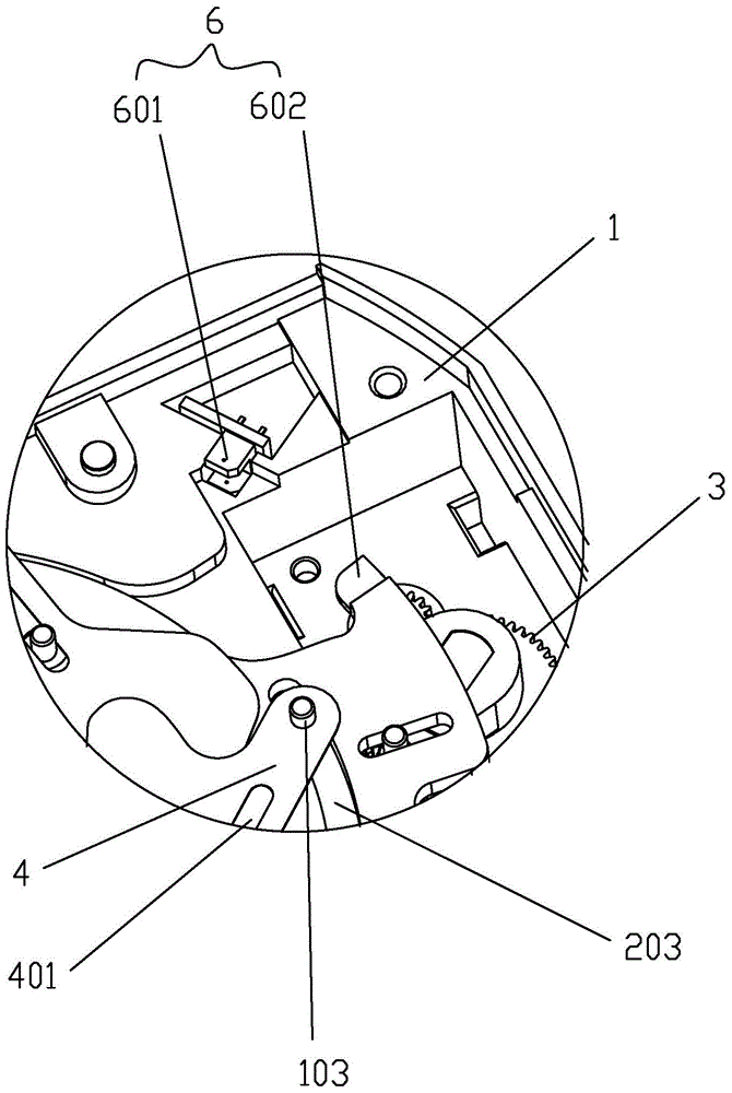
[0027] Such as Figure 1 to Figure 7 As shown, a stepping aperture device with a photoelectric detection device includes a base 1, the base 1 is provided with a base through hole 101 and a boss 102 surrounding the base through hole 101, and the boss 102 is sleeved There is a turntable 2, the turntable 2 is provided with a turntable through hole 201 communicating with the base through hole 101, the base 1 is provided with a drive device 3 for driving the turntable 2 to rotate, and the base 1 is located on the boss 102 is provided with a plurality of protruding columns 103 distributed in a circular array, and the turntable 2 is provided with a plurality of columns 202 distributed in a circular array, and each of the protruding columns 103 is provided with a blade 4 that can rotate around it. The blade 4 is provided with a strip-shaped hole 401 for the dial 202 to slide in wh...


PUM


Abstract

The invention discloses a stepping aperture device with a photoelectric detection device. The stepping aperture device comprises a base, a base through hole and a boss are arranged on the base, the boss is sleeved with a rotating disc, and a rotating disc through hole is formed in the rotating disc and communicated with the base through hole. A driving device is arranged on the base and used for driving the rotating disc to rotate. Multiple protrusive pillars are circumferentially distributed on the part, located on the periphery of the boss, of the base in an arrayed mode. Multiple poking pillars are circumferentially distributed on the rotating disc in an arrayed mode. Each protrusive pillar is provided with a blade which can rotate around the protrusive pillar. The blades are provided with strip-shaped holes, wherein in the rotating process of the rotating disc, the poking pillars slide inside the strip-shaped holes to drive the blades to rotate around the protrusive pillars. An aperture can be defined by the inner side faces of the multiple blades, wherein the area of the aperture changes along with rotating of the blades, and the photoelectric detection device is further arranged on the base and used for detecting the position of the rotating disc to judge whether the aperture is fully closed or not. A cover plate is fixedly connected to the base and provided with a cover plate through hole communicated with the base through hole. The fully-closed position of the aperture can be detected accurately, and the size adjusting accuracy of the aperture can be improved.

Description

【Technical field】 [0001] The invention relates to a stepping aperture device, more specifically a stepping aperture device with a photoelectric detection device. 【Background technique】 [0002] In the field of the aperture system of the surveillance lens, the driving form of the aperture is gradually becoming intelligent and controllable. The traditional solenoid valve type aperture is composed of a driving coil and a damping coil, and then the Hall element is used to complete the opening and closing of the aperture. control. In the power-off state, the aperture is fully closed. If you want to maintain a certain size of aperture, you need to keep the power on. Once the power is off, the aperture is fully closed again. The stepping aperture is controlled by a stepping motor, and the power can be cut off when the aperture is adjusted to the required size. The size and area of ​​the aperture can be controlled by the number of steps of the stepping motor. Its function is supe...

Claims


Application Information

Patent Timeline
Patent Type & Authority Patents(China)
IPC IPC(8): G03B9/06
Inventor 刘辉蔡宾吕祖文邱盛平
Owner UNION OPTECH
Why Eureka
Try Eureka