Differential protection device based on optics current sensors
A technology of differential protection device and current sensor, which is applied in the direction of emergency protection circuit device, measuring device, measuring current/voltage, etc., can solve the problem of carrier optical signal optical power loss and other problems, and achieve the goal of reducing optical power loss and lowering requirements Effect
- Summary
- Abstract
- Description
- Claims
- Application Information
AI Technical Summary
Problems solved by technology
Method used
Image
Examples
specific Embodiment approach 1
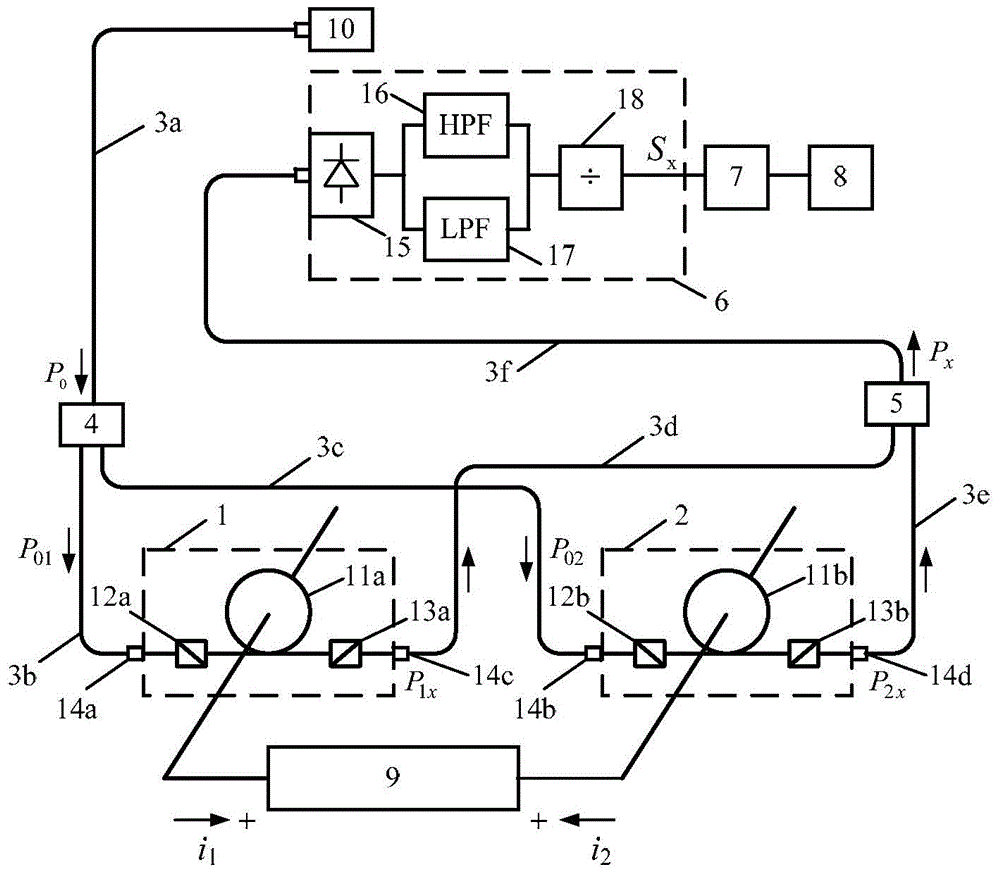
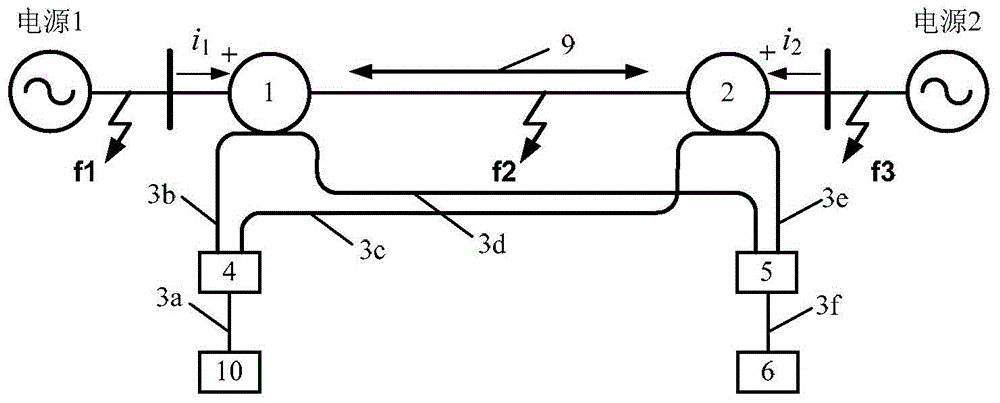
[0046] Specific implementation mode one: the following combination figure 1 and figure 2 Describe this embodiment, the optical current sensor-based differential protection device described in this embodiment includes a first optical current sensor 1, a second optical current sensor 2, a light source 10, a first multi-mode optical fiber 3a, a second multi-mode optical fiber Mode optical fiber 3b, third multimode optical fiber 3c, fourth multimode optical fiber 3d, fifth multimode optical fiber 3e, sixth multimode optical fiber 3f, multimode optical fiber beam splitter 4, multimode optical fiber beam combiner 5 and optical signal processing Unit 6;
[0047] The first optical current sensor 1 comprises: a first multimode fiber collimator 14a, a first polarizer 12a, a first Faraday magneto-optical element 11a, a first analyzer 13a and a third multimode fiber collimator 14c, and The first polarizer 13a is arranged at an angle of 45° relative to the first polarizer 12a;
[0048...
specific Embodiment approach 2
[0093] Embodiment 2: This embodiment further limits the differential protection device based on the optical current sensor described in Embodiment 1. In this embodiment, the optical signal processing unit 6 includes a photoelectric converter 15 and a high-pass filter circuit 16 , low-pass filter circuit 17 and ratio calculator 18;
[0094] The photoelectric converter 15 is used to receive the optical signal of the sixth multimode optical fiber 3f, and transform the optical signal into an electrical signal, and simultaneously send it to the high-pass filter circuit 16 and the low-pass filter circuit 17;
[0095] The high-pass filter circuit 16 and the low-pass filter circuit 17 are used to separate the received electrical signal into a DC component and an AC component;
[0096] The ratio calculator 18 is used to receive the DC component and the AC component, and divide the AC component by the DC component to obtain a differential current output signal.
[0097] Set the sensiti...
specific Embodiment approach 3
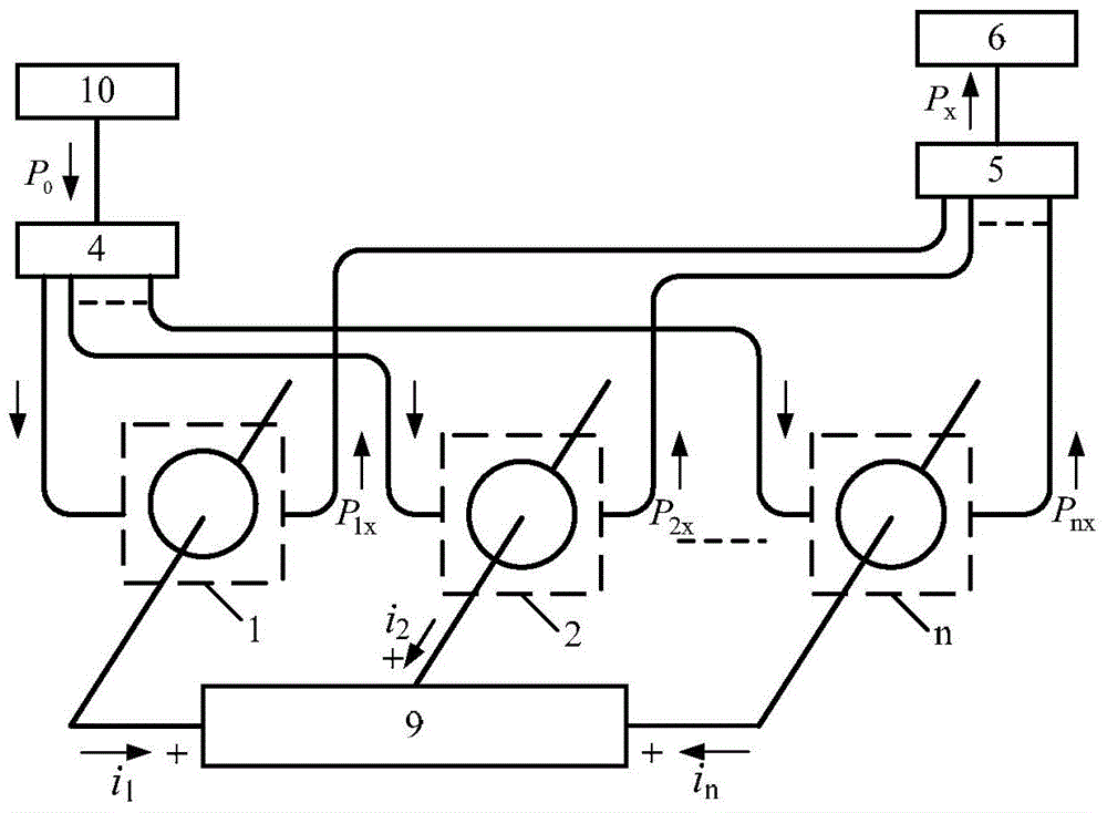
[0099] Specific implementation mode three: the following combination image 3 Describe this embodiment, the structural diagram of the optical current sensor-based differential protection device for the multi-port protection interval described in this embodiment, the number of ports n is greater than 2, it mainly includes: n optical current sensors (1, 2...n); light source 10; multimode optical fiber; multimode optical fiber beam splitter 4; multimode optical fiber beam combiner 5; optical signal processing unit 6;
[0100] Among them, n optical current sensors (1, 2...n) contain exactly the same type and quantity of optical elements; the multimode fiber beam splitter 4 is a 1×n multimode fiber beam splitter; the multimode fiber beam combiner 5 is an n×1 multimode fiber bundle combiner.
[0101] n optical current sensors (1, 2...n) are respectively distributed in each port of the multi-port protection interval 9; each port current i is set 1 i 2 ...i n The direction flowing...
PUM
 Abstract
Description
Claims
Application Information
 - R&D
- Intellectual Property
- Life Sciences
- Materials
- Tech Scout
- Unparalleled Data Quality
- Higher Quality Content
- 60% Fewer Hallucinations
Browse by: Latest US Patents, China's latest patents, Technical Efficacy Thesaurus, Application Domain, Technology Topic, Popular Technical Reports.
© 2025 PatSnap. All rights reserved.Legal|Privacy policy|Modern Slavery Act Transparency Statement|Sitemap|About US| Contact US: help@patsnap.com


