Differential protection device based on optical current sensor

A technology of differential protection device and current sensor, which is applied in the direction of emergency protection circuit device, measuring device, measuring current/voltage, etc., can solve the problem of carrier optical signal optical power loss and other problems, and achieve the goal of reducing optical power loss and lowering requirements Effect

Active Publication Date: 2017-02-22
HARBIN INST OF TECH +3
View PDF6 Cites 0 Cited by
  • Summary
  • Abstract
  • Description
  • Claims
  • Application Information

AI Technical Summary

Problems solved by technology

[0030] The present invention aims to solve the problem of serious loss of optical power of the carrier optical signal of the output optical signal of the cascaded optical current sensor, thereby providing a differential protection device based on the optical current sensor

Method used


Image

  • Differential protection device based on optical current sensor
  • Differential protection device based on optical current sensor
  • Differential protection device based on optical current sensor

Examples


specific Embodiment approach 1

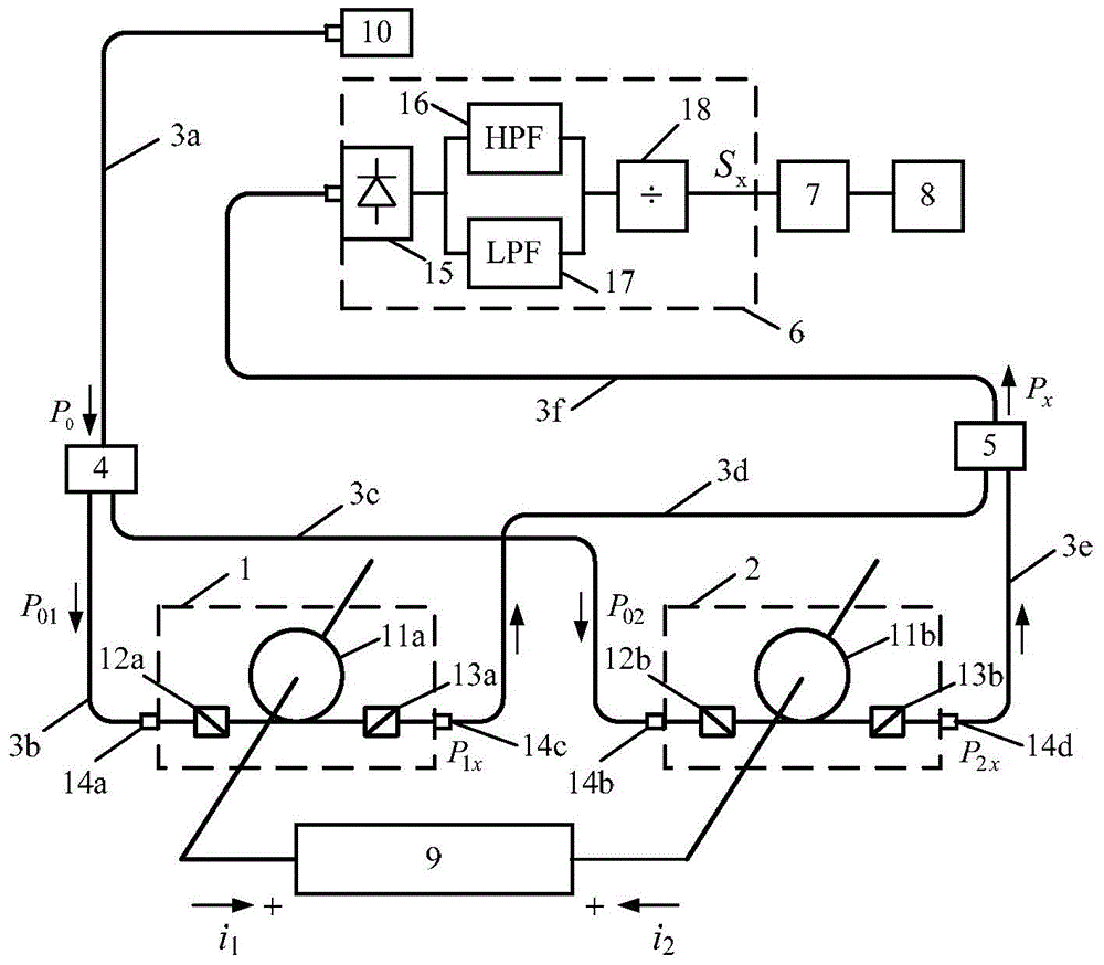
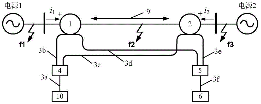
[0046] Specific implementation mode one: the following combination figure 1 with figure 2 Describe this embodiment, the optical current sensor-based differential protection device described in this embodiment includes a first optical current sensor 1, a second optical current sensor 2, a light source 10, a first multi-mode optical fiber 3a, a second multi-mode optical fiber Mode optical fiber 3b, third multimode optical fiber 3c, fourth multimode optical fiber 3d, fifth multimode optical fiber 3e, sixth multimode optical fiber 3f, multimode optical fiber beam splitter 4, multimode optical fiber beam combiner 5 and optical signal processing Unit 6;

[0047] The first optical current sensor 1 comprises: a first multimode fiber collimator 14a, a first polarizer 12a, a first Faraday magneto-optical element 11a, a first analyzer 13a and a third multimode fiber collimator 14c, and The first polarizer 13a is arranged at an angle of 45° relative to the first polarizer 12a;

[004...

specific Embodiment approach 2

[0093] Embodiment 2: This embodiment further limits the differential protection device based on the optical current sensor described in Embodiment 1. In this embodiment, the optical signal processing unit 6 includes a photoelectric converter 15 and a high-pass filter circuit 16 , low-pass filter circuit 17 and ratio calculator 18;

[0094] The photoelectric converter 15 is used to receive the optical signal of the sixth multimode optical fiber 3f, and transform the optical signal into an electrical signal, and simultaneously send it to the high-pass filter circuit 16 and the low-pass filter circuit 17;

[0095] The high-pass filter circuit 16 and the low-pass filter circuit 17 are used to separate the received electrical signal into a DC component and an AC component;

[0096] The ratio calculator 18 is used to receive the DC component and the AC component, and divide the AC component by the DC component to obtain a differential current output signal.

[0097] Set the sensiti...

specific Embodiment approach 3

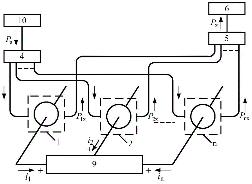
[0099] Specific implementation mode three: the following combination image 3 Describe this embodiment, the structural diagram of the optical current sensor-based differential protection device for the multi-port protection interval described in this embodiment, the number of ports n is greater than 2, it mainly includes: n optical current sensors (1, 2...n); light source 10; multimode optical fiber; multimode optical fiber beam splitter 4; multimode optical fiber beam combiner 5; optical signal processing unit 6;

[0100] Among them, n optical current sensors (1, 2...n) contain exactly the same type and quantity of optical elements; the multimode fiber beam splitter 4 is a 1×n multimode fiber beam splitter; the multimode fiber beam combiner 5 is an n×1 multimode fiber bundle combiner.

[0101] n optical current sensors (1, 2...n) are respectively distributed in each port of the multi-port protection interval 9; each port current i is set 1 i 2 ... i n The direction flowin...


PUM


Abstract

The invention relates to a power system relay protection device, in particular to a differential protection device based on optics current sensors to solve the problem that the power loss of a carrier optical signal output by the optics current sensor in cascading is serious. The first optics current sensor and the second optics current sensor are arranged at the two ends of a protection section, a light source is connected with the incidence end of a multimode optical fiber beam splitter through multimode optical fiber, the output end of the multimode optical fiber beam splitter is connected with the incidence end of the first optics current sensor and the incidence end of the second optics current sensor through multimode optical fiber, the emitting end of the first optics current sensor and the emitting end of the second optics current sensor are respectively connected with the incidence end of the multimode optical fiber beam splitter through multimode optical fiber, and the emitting end of the multimode optical fiber beam splitter is connected with the input end of an optical signal processing unit through multimode optical fiber.

Description

technical field [0001] The invention relates to a power system relay protection device. Background technique [0002] At present, the relay protection device in the power system transmits the current information detected by the conventional electromagnetic current transformer to the relay protection device in the form of an electrical signal, and the calculation and calculation of the fault criterion are carried out in the relay protection device. The result is judged. In order to realize the low cost and light weight of the relay protection device, JP-A-2000-59987 and JP-11-224821 (Japan) have proposed a protection relay device based on an optical current sensor with a differential operation function It replaces the current measurement method based on the current winding type current transformer. The relay protection device described in this patent uses two optical current sensors in a cascaded manner to obtain a differential current output signal proportional to the flow...

Claims


Application Information

Patent Timeline
Patent Type & Authority Patents(China)
IPC IPC(8): H02H7/26G01R19/00
Inventor 于文斌张国庆郭志忠宋平黄华炜李传生申岩王贵忠
Owner HARBIN INST OF TECH
Why Eureka
Try Eureka