
An Asymmetric Rotor Linear Rotary Motion Converter

A rotary motion, asymmetric technology, applied in the field of power transmission, can solve the problems of increased vibration of the converter, reduced operating efficiency, increased torque ripple, etc., to avoid noise and vibration, reduce torque ripple, reduce tooth Effect of slot torque

Active Publication Date: 2017-04-19
SOUTHEAST UNIV
View PDF4 Cites 0 Cited by
  • Summary
  • Abstract
  • Description
  • Claims
  • Application Information

AI Technical Summary

Problems solved by technology

[0004] The traditional permanent magnet rotor uses high-performance permanent magnet materials to obtain high magnetic energy density, but also increases the torque ripple of the rotor, resulting in aggravated vibration of the converter, increased noise, and reduced operating efficiency

Method used


Image

  • An Asymmetric Rotor Linear Rotary Motion Converter
  • An Asymmetric Rotor Linear Rotary Motion Converter
  • An Asymmetric Rotor Linear Rotary Motion Converter

Examples


Embodiment 1

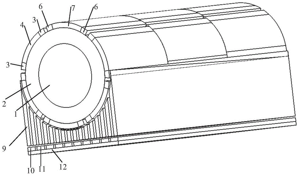
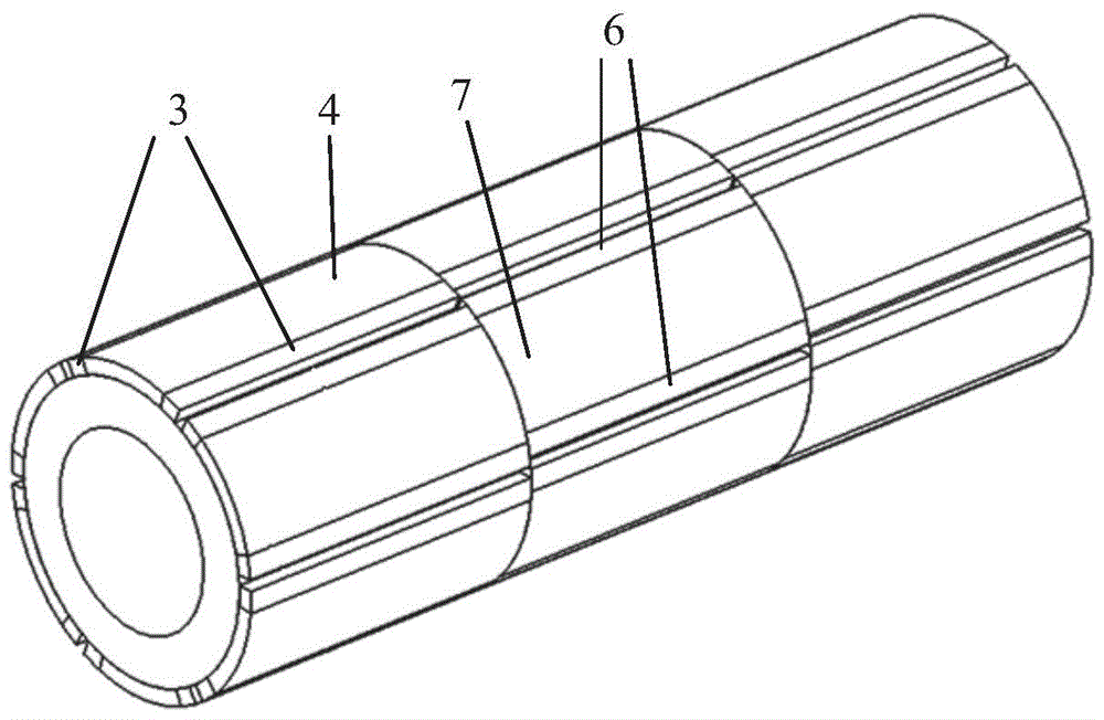
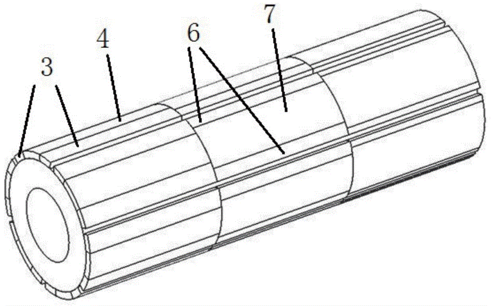
[0031]Embodiment 1: An asymmetric rotor linear rotary motion converter, including a rotary unit, a linear unit, and a magnetic modulation mechanism, the magnetic modulation mechanism is fixedly arranged between the rotary unit and the linear unit. Wherein, the rotating unit includes a rotating shaft 1, a rotor core 2 and a permanent magnet; In this embodiment, the permanent magnets include two pairs of pole permanent magnets, the pole arc coefficient is 0.6, and the permanent magnets include N-pole permanent magnets 4 and S-pole permanent magnets 7 of NdFeB materials with the same central angle, inner and outer diameters and axial lengths. , also includes N-pole permanent magnet 3 and S-pole permanent magnet 6 of ferrite material with equal central angle, inner and outer diameter and axial length. N-pole permanent magnet 4 and S-pole permanent magnet 7 of NdFeB material, and N-pole permanent magnet 3 and S-pole permanent magnet 6 of ferrite material are tile-shaped permanent m...

Embodiment 2

[0037] Embodiment 2: An asymmetric rotor linear rotary motion converter, including a rotary unit, a linear unit, and a magnetic modulation mechanism, and the magnetic modulation mechanism is fixedly arranged between the rotary unit and the linear unit. Wherein, the rotating unit includes a rotating shaft 1 , a rotor core 2 and a permanent magnet. The rotating shaft 1 passes through the shaft hole of the rotor core 2 and is fastened together with the rotor core 2 . The permanent magnet is attached to the surface of the rotor core 2 . In this embodiment, the permanent magnets include two pairs of pole permanent magnets, and the pole arc coefficient is 0.6. The permanent magnets include N-pole permanent magnets 4 and S-pole permanent magnets 7 of NdFeB materials, and N-pole permanent magnets of ferrite materials. 3 and S pole permanent magnet 6. N-pole permanent magnet 4 and S-pole permanent magnet 7 of NdFeB material, and N-pole permanent magnet 3 and S-pole permanent magnet 6 o...


PUM


Abstract

The invention discloses a linear and rotary motion converter for an asymmetric rotor. The linear and rotary motion converter can transmit torque and mechanical energy to achieve mutual conversion of linear motion and rotary motion. The linear and rotary motion converter for the asymmetric rotor comprises a rotary unit, a linear unit and a magnetism-adjusting mechanism, wherein the rotary unit comprises a rotor iron core and permanent magnet poles, and the permanent magnet poles are formed by splicing NdFeB permanent magnets and ferrite permanent magnets and are stuck onto the surface of the rotor iron core by adopting a segmental structure; the linear unit comprises a rotor yoke and permanent magnet poles, and radially-magnetized N-pole permanent magnets and radially-magnetized S-pole permanent magnets are stuck onto the surface of the rotor yoke alternately; the magnetism-adjusting mechanism consists of a magnetism-adjusting iron blocks for guiding magnetism. The rotary unit adopts a novel permanent magnetic rotor structure, so that the torque ripple is effectively reduced, jitter and loss of converter are reduced and the moving stability and the energy conversion efficiency of the converter are improved; the low-cost permanent magnets are used together with the high-cost permanent magnets, so that the manufacturing cost of the converter is reduced and the cost performance is improved.

Description

technical field [0001] The invention relates to an asymmetrical rotor linear rotary motion converter, which is suitable for non-contact variable speed driving occasions and belongs to the technical field of power transmission. Background technique [0002] In the fields of industrial and agricultural production, national defense, aviation, aerospace and other fields, it is often necessary to change rotary motion into linear motion, or convert linear motion into rotary motion. According to different applications, people have developed various conversion devices or equipment to meet the above requirements, such as rack and pinion, chain, wire rope, transmission belt, screw rod, crank connecting rod, slider mechanism, cam ejector mechanism, etc. In these transforming devices, linear motion parts and rotary motion parts are in contact with each other, causing problems of friction, vibration, noise, and the like. [0003] Permanent magnet rack and pinion is a non-contact transmi...

Claims


Application Information

Patent Timeline
Patent Type & Authority Patents(China)
IPC IPC(8): H02K49/10
Inventor 付兴贺王标林明耀
Owner SOUTHEAST UNIV
Learn More