
Warm press forming method and automobile frame component

A molding method and warm pressing technology, which is applied to vehicle parts, railway car body parts, heat treatment furnaces, etc., and can solve problems such as poor dimensional accuracy, poor press formability, and limited parts

Active Publication Date: 2014-11-19
JFE STEEL CORP
View PDF8 Cites 36 Cited by
  • Summary
  • Abstract
  • Description
  • Claims
  • Application Information

AI Technical Summary

Problems solved by technology

However, high-strength steel sheets generally have poor press formability, and the shape change (springback) caused by elastic recovery after mold release is large, and poor dimensional accuracy is prone to occur, so the parts that are currently applied to press forming are limited.

Method used


Image

  • Warm press forming method and automobile frame component
  • Warm press forming method and automobile frame component
  • Warm press forming method and automobile frame component

Examples


Embodiment 1

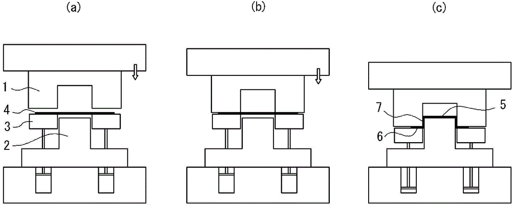
[0200] Steel plates with a thickness of 1.6 mm and a tensile strength of 440 MPa class to 1180 MPa class were heated under the conditions shown in Table 1, and then formed by drawing forming into Figure 5 (a) shows the upper pressure plate of the center pillar as one of the car frame components.

[0201] Here, an electric furnace is used for heating the steel plate. The time in the furnace was set to 300 seconds, so that the entire billet was heated with a uniform temperature distribution. The heated slab was taken out of the furnace, fed into the press after a transfer time of 10 seconds, and formed by varying the holding time at the bottom dead center of the forming as shown in Table 1.

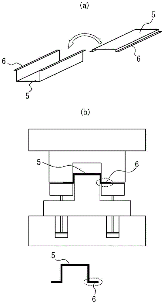
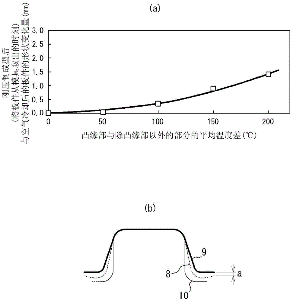
[0202] Immediately thereafter, the temperature difference between the flange portion and the portion other than the flange portion of the formed panel was measured. That is, using a non-contact thermometer, on the flange portion of the plate ( Figure 5 The position indicated by point X...

Embodiment 2

[0210] Molten steel having the composition shown in Table 2 was smelted in a converter and cast by a continuous casting method to produce a thick slab (steel raw material). These thick billets (steel raw materials) were heated to the heating temperature shown in Table 3, soaked and held, and after rough rolling, they were finished rolled and cooled under the hot rolling conditions shown in Table 3, and coiled into coils. Made into a hot-rolled steel plate (thickness: 1.6mm). It should be noted that the steel sheets a, i, k, and m are heated to 700°C in a continuous hot-dip galvanizing line, and then immersed in a hot-dip galvanizing bath with a liquid temperature of 460°C to form a hot-dip galvanized layer on the surface. , and then perform alloying treatment on the coating layer at 530° C. to form an alloyed hot-dip galvanized layer. It should be noted that the plating adhesion is 45g / m 2 .


PUM

PropertyMeasurementUnit
Plate thicknessaaaaaaaaaa
Tensile strengthaaaaaaaaaa
Adhesionaaaaaaaaaa

Abstract

By the present invention, during forming of a steel sheet having a tensile strength of 400 MPa or greater into a press-formed part comprising a flange part and other portions by press forming, by heating the steel sheet to a temperature range of 400-700°C and then press forming the heated steel sheet using draw forming, at which time this state is maintained for 1 to 5 seconds at the bottom dead center of forming, shape changes such as springback can be suppressed, the dimensional precision of a panel can be enhanced, and the desired mechanical characteristics can easily be obtained in the press-formed part.

Description

technical field [0001] The present invention relates to a warm press forming method capable of suppressing poor dimensional accuracy due to shape changes such as springback that occurs when high-strength steel sheets are press-formed. [0002] Furthermore, the present invention relates to an automobile frame member manufactured by the above-mentioned warm press molding method. Background technique [0003] The application of high-strength steel plates to vehicle components has been studied in order to balance the weight reduction of the vehicle body for the purpose of increasing fuel consumption ratings and the improvement of collision safety for passenger protection. However, high-strength steel sheets generally have poor press-formability, and have a large shape change (springback) due to elastic recovery after mold release, and are prone to poor dimensional accuracy. Therefore, the parts to which press-forming is currently applied are limited. [0004] Therefore, in orde...

Claims


Application Information

Patent Timeline
IPC IPC(8): B21D22/20B21D53/88C21D9/00C21D9/46C22C38/00C22C38/14C22C38/60
CPCC22C38/14B21D22/208C22C38/04C21D9/46C22C38/001C22C38/002C21D2211/004C22C38/02B21D53/88C21D8/0226C22C38/12C22C38/00C22C38/60C22C38/06C21D1/673B21D22/20C21D2211/005C23C2/06C23C2/28C22C38/005C22C38/007C22C38/08C22C38/105C22C38/20C22C38/24C22C38/28C22C38/44C22C38/50C23C2/29B21D22/02B21J1/06B21K7/12
Inventor 时田裕一玉井良清簑手彻藤田毅
Owner JFE STEEL CORP
Learn More