
A spiral maxillary sinus lifting device and lifting system

A maxillary sinus and lifting rod technology, which is applied to the field of lifting devices and lifting systems in the maxillary sinus, can solve the problems of implant socket damage, unstable retention, poor bone condition, etc., so as to avoid errors and tediousness, and improve surgical safety. , to avoid the effect of insufficient vision

Active Publication Date: 2017-12-15
6D DENTAL TECH
View PDF7 Cites 0 Cited by
  • Summary
  • Abstract
  • Description
  • Claims
  • Application Information

AI Technical Summary

Problems solved by technology

[0005] The disadvantages of this maxillary sinus bottom lifting device are: 1. The base is connected to the bone tissue in the implant socket through threads, and when the maxillary sinus is lifted, the active force is directly transmitted to the thread joint of the bone tissue, which is very easy to cause damage to the implant socket; The bone quality of the teeth is generally poor, the bone density is low, and the base is retained by the alveolar bone, which is unstable
2. There is no uniform benchmark for the depth of the hole preparation and the lifting height during the operation. The height of the screw lifting must be measured by the doctor while operating the screw, and the accuracy is low.

Method used


Image

  • A spiral maxillary sinus lifting device and lifting system
  • A spiral maxillary sinus lifting device and lifting system
  • A spiral maxillary sinus lifting device and lifting system

Examples


Embodiment Construction

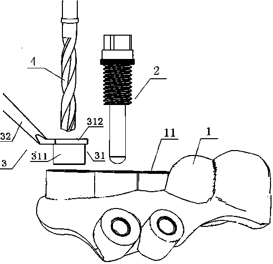
[0025] A lifting device for the maxillary sinus, comprising a positioning guide plate 1, a lifting rod and a ring block gauge 22.

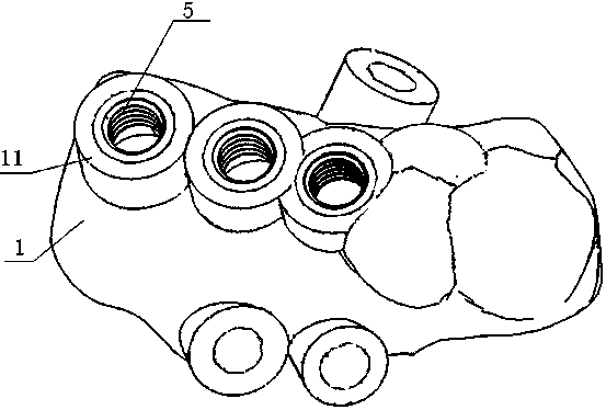
[0026] Such as figure 2 As shown, the positioning guide plate 1 has a guide hole 11 corresponding to the implant socket, and a threaded sleeve 5 is fixed in the guide hole 11, the outer wall of the threaded sleeve 5 is adapted to the guide hole 11, and the inner wall of the threaded sleeve 5 has internal threads .

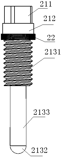
[0027] Such as image 3 and Figure 4 As shown, the lifting rod is composed of a force receiving part 211, a retaining ring 212 and a working part, the force receiving part 211 and the working part are separated by the retaining ring 212, and the working part includes a threaded section 2131, a head 2132 and the threaded section 2131 and the head The connecting section 2133 between the parts 2132 and the threaded section 2131 are engaged with the internal thread of the threaded sleeve 5 .

[0028] Such as Figure 5 As shown, the ...


PUM


Abstract

The invention discloses an internal maxillary sinus lifting device which comprises a positioning guide plate, a lifting rod and an annular sleeve block gauge, wherein guide holes corresponding to planting pits are formed in the positioning guide plate; threaded sleeves are fixed inside the guide holes; the outer walls of the threaded sleeves are adapted to the guide holes; internal threads are formed in the inner walls of the threaded sleeves; the lifting rod consists of a forced part, a baffle ring and a working part; the forced part is portioned from the working part by the baffle ring; the working part comprises a threaded section, a head part and a connecting section; the threaded section is meshed with the internal threads inside the threaded sleeves; internal threads are formed inside the annular sleeve block gauge. In the operation process, the top surfaces of the guide holes are taken as positioning reference surfaces, the length of the working part of the lifting rod is greater than the distance from the top surfaces of the guide holes to the bottoms of the planting pits, the internal lifting height of the lifting rod is as shown in the formula. An internal maxillary sinus lifting system consists of the internal maxillary sinus lifting device and a hole formation tool, wherein the hole formation tool comprises a drill bit and a pressing plate. The internal maxillary sinus lifting device has the advantages that the lifting precision is high and the internal lifting device fixation can be achieved without damaging the planting pits.

Description

technical field [0001] The invention relates to a maxillary sinus lifting device and a lifting system. Background technique [0002] When the maxillary posterior teeth are missing, the bottom wall of the maxillary sinus usually has insufficient height of the implant bone due to the absorption of the alveolar ridge. At this time, once the implant is implanted, it may penetrate the maxillary sinus wall and mucous membrane. In order to place implants, it is often necessary to create a space in the maxillary sinus floor and maxillary mucosa, and implant some synthetic bone substitutes in this space to increase the distance from the alveolar ridge to the maxillary sinus floor and lift the maxillary sinus floor To the position that meets the needs of the implant, so that it is possible to place the implant in the maxilla. This surgical procedure is called maxillary sinus lift. When the traditional maxillary sinus lifting operation is performed, the implant socket is prepared on t...

Claims


Application Information

Patent Timeline
Patent Type & Authority Patents(China)
IPC IPC(8): A61C8/00
Inventor 彭伟于长洋游嘉泮海松
Owner 6D DENTAL TECH
Learn More