Punching device with thin film positioning function and laser hole cutting function

A laser cutting and thin film technology, applied in the field of sheet metal processing, can solve the problems of many burrs on the edge of the hole, cannot be adjusted in real time, and low punching quality, and achieve the effect of less punching burrs, precise positioning, and high processing efficiency

Inactive Publication Date: 2014-11-26
SUZHOU JINGYU AUTOMATION TECH
View PDF5 Cites 17 Cited by
  • Summary
  • Abstract
  • Description
  • Claims
  • Application Information

AI Technical Summary

Problems solved by technology

The disadvantages of the above-mentioned punching device or punching machine are: punching can only be performed according to the preset punching press

Method used


Image

  • Punching device with thin film positioning function and laser hole cutting function
  • Punching device with thin film positioning function and laser hole cutting function

Examples


Embodiment Construction

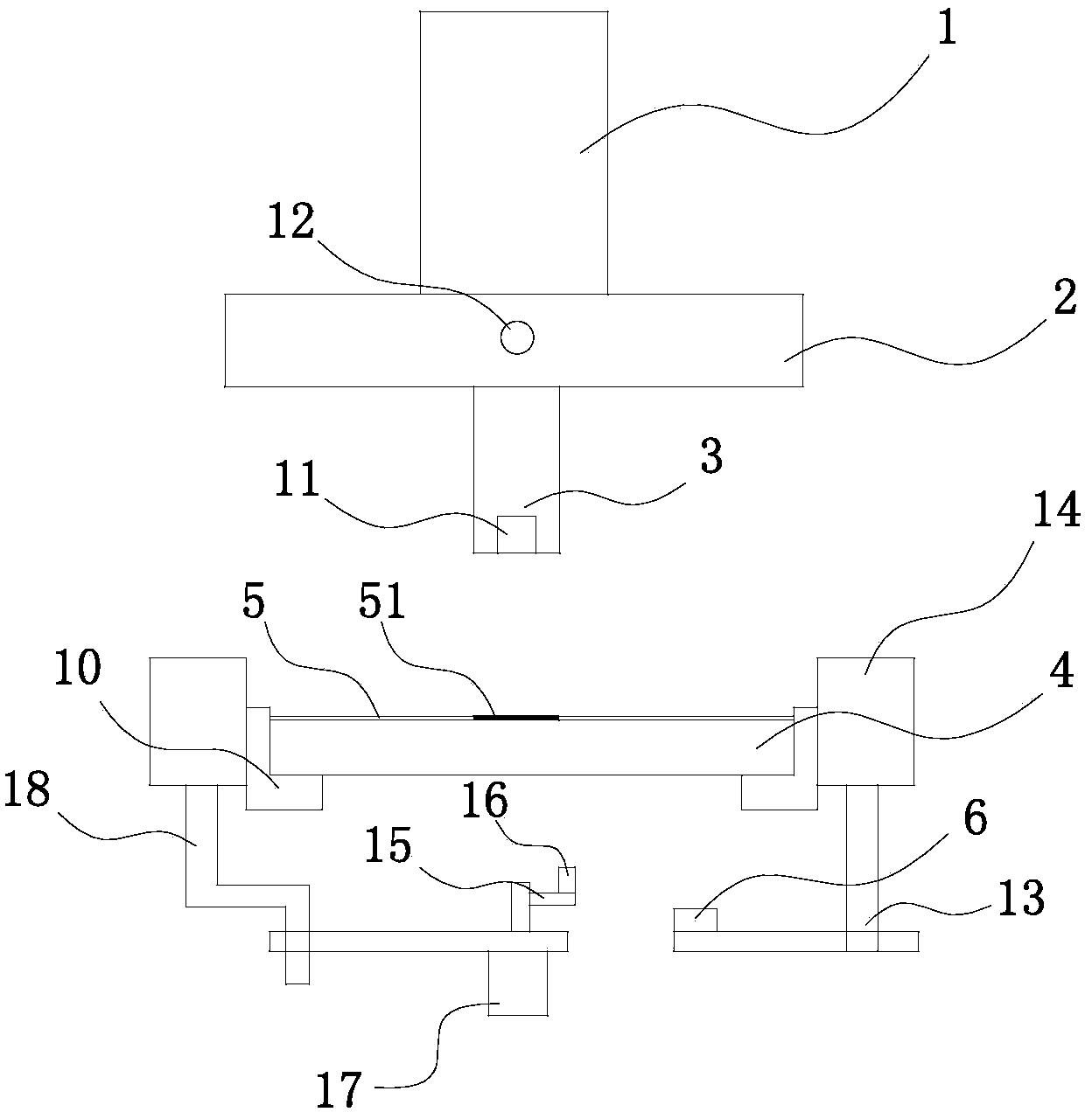
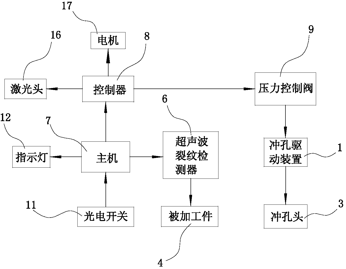
[0011] The specific implementation manner of the present invention will be described below in conjunction with the accompanying drawings.

[0012] like figure 1 and figure 2 As shown, the punching device with film positioning and laser cutting in this embodiment includes a punching drive device 1, an upper template 2, a punching head 3, and a clamping device 10 located below the punching head 3. The workpiece 4 is installed in the device 10, and also includes a host computer 7, a controller 8, a pressure control valve 9 and an ultrasonic crack detector 6 located below the workpiece 4; the punching head 3 is equipped with a photoelectric switch 11, and the workpiece 4 Covered with a film 5, the film 5 has a color code 51 for photoelectric switch 11 detection; the clamping device 10 is installed on the support 14, and the lower surface side of the support 14 is equipped with an ultrasonic crack detector 6 by means of a connecting rod 13, and the other One side installs laser ...


PUM


Abstract

The invention relates to a punching device with a thin film positioning function and a laser hole cutting function. The punching device comprises a punching drive device, an upper template, a punching head and a clamping device located below the punching head. A machined piece is arranged in the clamping device. The punching device further comprises a main machine, a controller, a pressure control valve and an ultraviolet crack detector located below the machined piece. A photoelectric switch is arranged in the punching head. The machined piece is covered with thin film. The thin film is provided with a color scale used for photoelectric switch detection. The clamping device is arranged on a support. The ultrasonic crack detector is arranged on one side of the lower surface of the support with the help of a connecting rod. A laser hole cutting device is arranged on the other side of the lower surface of the support with the help of a bent frame. An indicator lamp connected with the main machine is arranged on the front side face of the upper template. Laser hole cutting and punching achieved through the punching head are combined so that punching can be conducted on metal plates, and the punching device is high in machining efficiency and less in punching burr; the punching device has the advantages of being accurate in positioning, convenient to operate and small in deformation.

Description

technical field [0001] The invention relates to the technical field of sheet metal processing, in particular to a sheet metal punching machine. Background technique [0002] Existing punching devices or punching machines all include a frame, a bottom mold fixed on the frame, an upper template that moves up and down relative to the frame, and a punch corresponding to the bottom mold is fixed on the upper template. , the upper template is connected with the oil cylinder or cylinder that drives it to move up and down. Driven by the oil cylinder or air cylinder, the upper template drives the punch to move up and down relative to the bottom die, so as to punch out the required holes on the workpiece between the punch and the bottom die. The disadvantages of the above-mentioned punching device or punching machine are: punching can only be performed according to the preset punching pressure, which cannot be adjusted in real time, the punching quality is low, the plate is easily de...

Claims


Application Information

Patent Timeline
IPC IPC(8): B21D28/26B21D43/00B21C51/00B23K26/382
Inventor 不公告发明人
Owner SUZHOU JINGYU AUTOMATION TECH
Why Eureka
Try Eureka