Multi-stage h-type soil retaining pile and its construction method

A construction method and technology for retaining piles, which are applied in excavation, infrastructure engineering, construction, etc., can solve the problems of easy collapse of foundation pit supporting structures, and achieve the effects of realizing multiple utilization, reducing construction difficulty and shortening construction period.

Active Publication Date: 2016-05-18
易朋莹 +1
View PDF6 Cites 0 Cited by
  • Summary
  • Abstract
  • Description
  • Claims
  • Application Information

AI Technical Summary

Problems solved by technology

[0005] One of the purposes of the present invention is to solve the problem that the existing foundation pit supporting structure is easy to collapse

Method used


Image

  • Multi-stage h-type soil retaining pile and its construction method
  • Multi-stage h-type soil retaining pile and its construction method
  • Multi-stage h-type soil retaining pile and its construction method

Examples


Embodiment 1

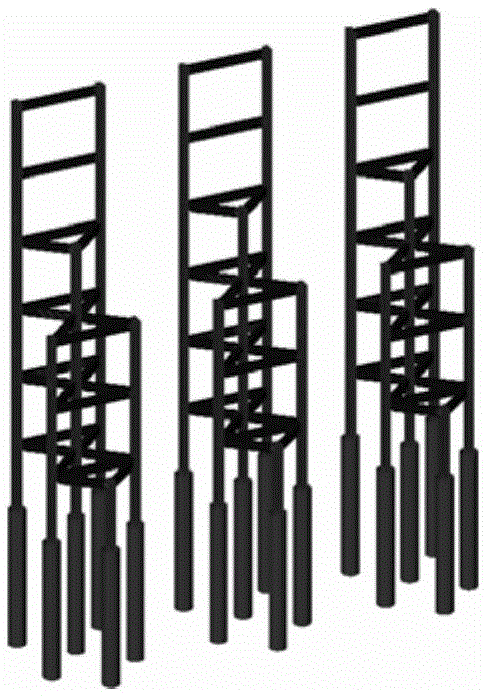
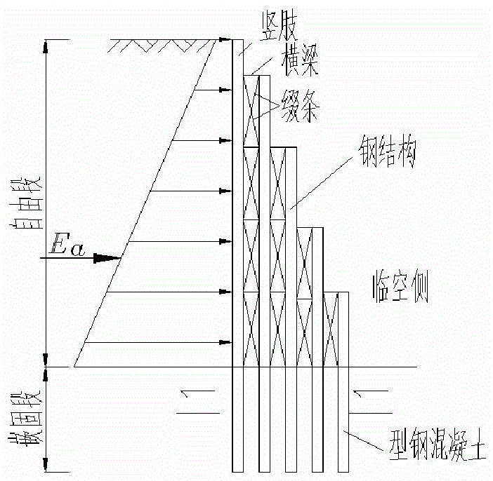
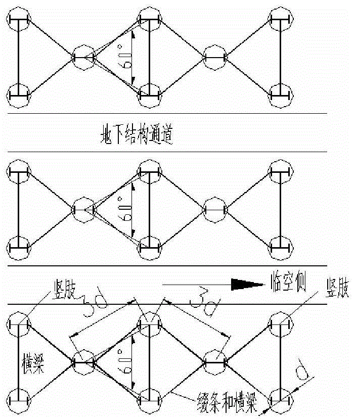
[0038] A multi-stage H-shaped soil retaining pile includes several circles of vertical limbs arranged in a foundation pit, and each circle of vertical limbs is composed of several vertical limbs. see Figure 6 , the figure is a top view of the foundation pit, which is surrounded by several vertical limbs to form three vertical limb circles. The lower end of each vertical limb is inserted into the bottom (base surface) of the foundation pit. The first circle of vertical limbs is in contact with the side wall of the foundation pit, from the first circle of vertical limbs to the Nth circle of vertical limbs ( Figure 6 Among them, N="three", the Nth circle of vertical limbs is the third circle of vertical limbs), gradually approaching the center of the foundation pit. Seen from the direction of the elevation, from the first circle of vertical limbs to the Nth circle of vertical limbs, the height exposed above the bottom of the foundation pit gradually decreases. This makes the...

Embodiment 2

[0042] The main structure of this embodiment is the same as that of Embodiment 1. It includes several vertical limbs with lengths S1, S2...Sn, wherein n is a natural number greater than or equal to 3, and S1>S2>...>Sn. A reinforcement cage is woven on the outer surface of the anchoring section of the vertical limb. Vertical limbs with lengths S1 , S2 . . . Sn are called vertical limbs Z1 , vertical limbs Z2 . . . vertical limbs Zn in sequence. Several vertical limbs Z1 form the first circle of vertical limbs, several vertical limbs Z2 form the second circle of vertical limbs, ..., several vertical limbs Zn form the Nth circle of vertical limbs .

[0043] Specifically, N in this embodiment = "five". That is, it includes several vertical limbs with lengths S1, S2, S3, S4 and S5, wherein S1=21 meters, S2=18 meters, S3=15 meters, S4=12 meters, and S5=9 meters. A reinforcement cage is woven on the outer surface of the anchoring section of the vertical limb. The vertical limbs ...

Embodiment 3

[0050] The main structure of this embodiment is the same as that of Embodiment 1.

[0051] Only, the vertical limbs can be perpendicular to the horizontal plane, or inclined (with a certain angle with the horizontal plane), that is, the angle between each vertical limb and the horizontal plane is α, 0°<α≤90°, preferably Ground: 30°≤α≤90°.

[0052] In addition, in this embodiment, the distance between each vertical limb circle can be close to 0. That is, each circle of vertical limbs is adjacent.

[0053] In one implementation manner, the first circle of vertical limbs is perpendicular to the horizontal plane, and the remaining circles of vertical limbs are all inclined.


PUM


Abstract

The invention provides a multi-stage h type retaining pile. The pile comprises multiple rows of vertical legs arranged in a foundation pit, and the vertical legs are steel columns. The first row of vertical legs makes contact with the inner wall face of the foundation pit. The heights are gradually decreased from the first row of vertical legs to the nth row of vertical legs. The vertical legs are perpendicular to the horizontal plane, and the lower ends of the vertical legs are inserted into the bottom face of the foundation pit. The parts, inserted into the bottom face of the foundation pit, of the vertical legs are embedded sections, and the parts, exposed out of the bottom face of the foundation pit, of the vertical legs are free sections. Concrete is poured into the embedded sections of the vertical legs, and the free sections of the vertical legs are filled with sandy soil and / or gypsum. The adjacent vertical legs are connected through beams and / or lacing bars.

Description

technical field [0001] The invention belongs to the field of geotechnical engineering, in particular to foundation pit engineering and temporary slope engineering. Background technique [0002] With the increasing number of high-rise (ultra-high) building projects at home and abroad, the number of foundation pit projects is increasing, the excavation depth of foundation pits is getting deeper and deeper, the excavation area is gradually increasing, and the surrounding sites are becoming narrower and narrower, and most of them are distributed In large and medium-sized cities with poor coastal engineering geological conditions and dense buildings (structures), there are more and more problems, which make the construction more and more difficult. Because in the process of deep foundation pit excavation and support, not only the stability of the foundation pit itself must be ensured, but also the safety and stability of adjacent building facilities must be ensured, so the safety...

Claims


Application Information

Patent Timeline
Patent Type & Authority Patents(China)
IPC IPC(8): E02D17/04E02D17/20
Inventor 易朋莹
Owner 易朋莹
Why Eureka
Try Eureka