
Anti-seismic foundation

A foundation and base technology, which is applied in basic structural engineering, protection devices, buildings, etc., can solve the problems of excessive absolute settlement, affect the performance of use, and cannot avoid shocks, and achieves reduction of uneven settlement and good shock absorption. , the effect of high vertical bearing capacity and horizontal shear resistance

Inactive Publication Date: 2014-11-26
CHENGDU LYUDI TECH
View PDF6 Cites 2 Cited by
  • Summary
  • Abstract
  • Description
  • Claims
  • Application Information

AI Technical Summary

Problems solved by technology

When building a building on a saturated soft soil foundation, because the saturated soft soil foundation has the characteristics of high water content, large void ratio and high compressibility, if it is not treated, there will be problems such as excessive absolute settlement, and the rotation Spray columns and concrete pouring piles are commonly used in various foundation treatments and foundation projects. Although they can play a certain role in strengthening the soil, because the material of the pile body is a mixture of cement and foundation soil, the strength of the pile body is low. It is prone to local compression damage, and cannot better play a shock-absorbing effect, affecting its performance

Method used


Image

  • Anti-seismic foundation

Examples


Embodiment Construction

[0013] The present invention is described in further detail now in conjunction with accompanying drawing. These drawings are all simplified schematic diagrams, which only illustrate the basic structure of the present invention in a schematic manner, so they only show the configurations related to the present invention.

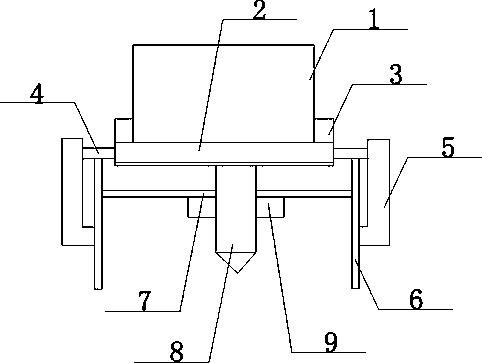
[0014] Such as figure 1 The preferred embodiment of the shown seismic foundation of the present invention includes a spacer wall 1, the spacer wall 1 is arranged on a group of pile foundations 2, the spacer wall 1 and the pile group foundation 2 are fixedly connected by cement mortar, and the spacer wall 1. Baffles 3 are installed on both sides. The outer surface of the baffle 3 is on the same horizontal line as the two ends of the pile group foundation 2. The two ends of the pile group foundation 2 are provided with connectors 4. The connectors 4 are arranged transversely through the pile group foundation 2. The cast-in-place pile 5 is arranged on the connec...


PUM


Abstract

The invention discloses an anti-seismic foundation. The anti-seismic foundation comprises a limiting wall. The limiting wall is arranged on a pile group foundation body. The limiting wall and the pile group foundation body are fixedly connected through cement mortal. Baffles are installed on the two sides of the limiting wall. The outer side face of each baffle and the two ends of the pile group foundation body are located on the same horizontal line. Connecting pieces are arranged at the two ends of the pile group foundation body. Each connecting piece penetrates through the pile group foundation body transversely. A cast-in-place pile is arranged on each connecting piece. Each cast-in-place pile is of an L-shaped structure. Each connecting piece transversely penetrates through the end, on the long edge, of the corresponding cast-in-place pile. A jet grouting pile is arranged between the end, on the short edge, of each cast-in-place pile and the corresponding connecting piece. A reinforced concrete base is transversely connected between the two jet grouting piles. A main pile column is vertically installed between the reinforced concrete base and the pile group foundation body. According to the anti-seismic foundation, the better anti-seismic function can be achieved, connection is reliable, the overall connection performance is high, the vertical bearing capacity and the horizontal shearing resistance are both high, a pile body is not prone to damage, the stratum adaptability is high, differential settlement of the foundation can be reduced, and the anti-seismic foundation can be better used.

Description

technical field [0001] The invention relates to a civil construction facility, in particular to an anti-seismic foundation. Background technique [0002] With the continuous development of human society and the continuous growth of population, more and more buildings have been built by human beings. In order to save land, many high-rise buildings have been built in major cities in China, and a large number of people and materials have gathered in these buildings. Wealth, so building security is particularly important. When building a building on a saturated soft soil foundation, because the saturated soft soil foundation has the characteristics of high water content, large void ratio and high compressibility, if it is not treated, there will be problems such as excessive absolute settlement, and the rotation Spray columns and concrete pouring piles are commonly used in various foundation treatments and foundation projects. Although they can play a certain role in strengthen...

Claims


Application Information

Patent Timeline
Patent Type & Authority Applications(China)
IPC IPC(8): E02D31/08
Inventor 梁枫
Owner CHENGDU LYUDI TECH
Learn More