
Piston connecting rod

A piston connecting rod, connecting rod small head technology, applied in the direction of connecting rods, engine components, shafts and bearings, etc., can solve the problems of slow market promotion and application, increased engine comprehensive manufacturing costs, high pin seat temperature, etc., to achieve The structure is simplified, the force is concentrated, and the effect of overcoming the locking of the piston pin

Active Publication Date: 2014-11-26
强道前
View PDF8 Cites 2 Cited by
  • Summary
  • Abstract
  • Description
  • Claims
  • Application Information

AI Technical Summary

Problems solved by technology

While strengthening the overall structural strength of the engine, it also increases the overall manufacturing cost of the engine
[0004] In the prior art, when the articulated piston is in use, the temperature of the pin seat is relatively high, and the lubrication is poor, and there are objective technical defects that are prone to piston pin locking or even piston failure.
In the evaluation of the beneficial effect of the hinged piston in the prior art, there are cognitive biases that are not known to those skilled in the art. Those skilled in the art are not aware that there are still such technical problems in the use of hinged pistons and lead to this problem. The immediate cause of the problem; this technical bias has led to slow market adoption and adoption of articulated pistons since they were produced in the 1980s

Method used


Image

  • Piston connecting rod
  • Piston connecting rod
  • Piston connecting rod

Examples


Embodiment Construction

[0027] The specific implementation manners of the present invention will be described in further detail below in conjunction with the accompanying drawings and embodiments. The following examples are only used to illustrate the present invention, but can not be used to limit the scope of the present invention.

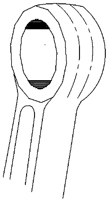
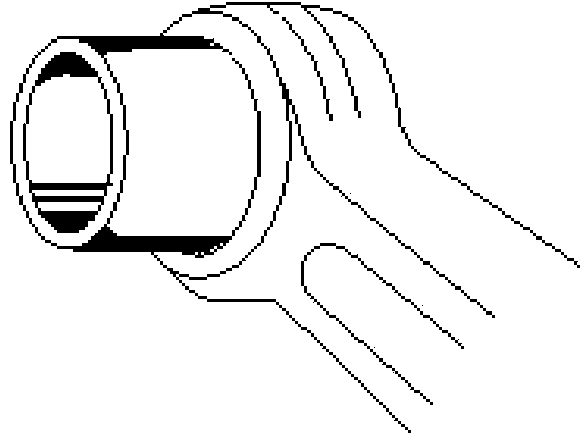
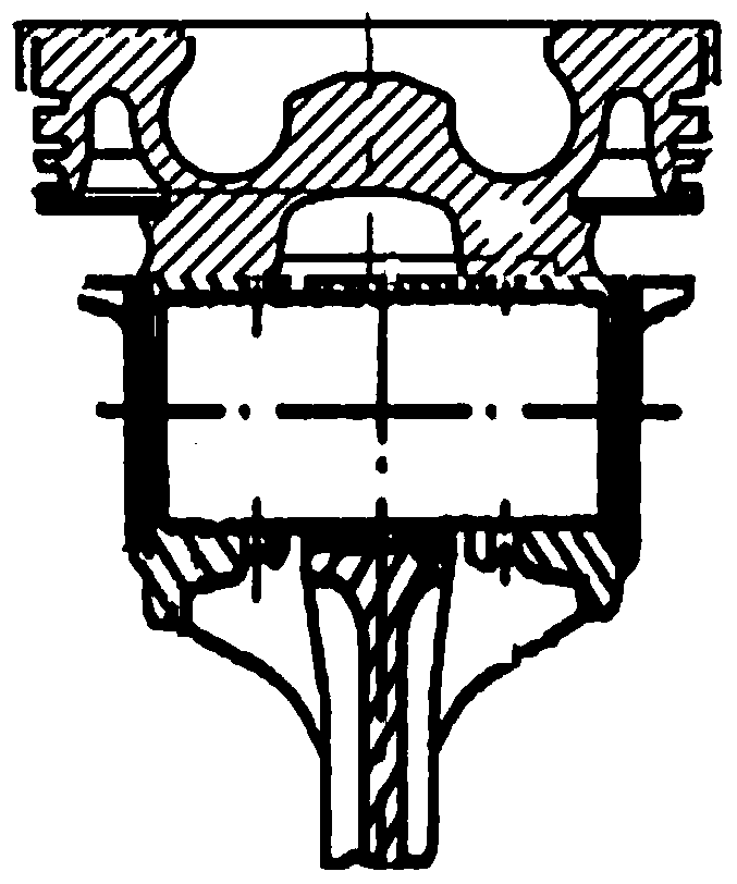
[0028] Figure 4~5 As shown, the present invention provides a piston connecting rod, including a connecting rod small end 1, a connecting rod large end and a shaft, the connecting rod small end 1 is a double-pin seat structure, and the double-pin seat structure is provided with and has a single The pin hole 2 required when the pin seat of the piston head of the pin seat structure is pin-connected; in the double pin seat structure, an oil collecting chamber 5 is arranged in the empty groove in the middle of the two pin seats near one end of the shaft.

[0029] Preferably, the oil collecting chamber is surrounded by the arc-shaped chamber bottom and the side walls insid...


PUM


Abstract

The invention relates to the technical field of the design of engine parts and specifically relates to a piston connecting rod. The piston connecting rod comprises a connecting rod small end (1), a connecting rod big end and a rod body; the connecting rod small end (1) is of a dual-pin boss structure; the dual-pin boss structure is provided with a pin hole (2) for realizing pin connection with a pin boss of a piston end of a single-pin boss structure. The dual-pin boss connecting rod small end adopted by the piston connecting rod provides structural support for a piston of the single-pin boss structure; the connection manner of the piston and the connecting rod small end is changed so that the assembled structure of the piston and the connecting rod can be more compact and the stress can be more concentrated. The dual-pin boss connecting rod small end adopted the piston connecting rod improves the motion load of the connecting rod structurally, and the oil collecting hole and the oil storage chamber of the connecting rod small end are formed to provide technical support for continuous cooling and lubrication of a piston pin. A bush is arranged at the pin hole of the connecting rod small end to provide further protection for the abrasive resistance of the pin hole at the connecting rod small end on the basis of ensuring cooling and lubrication.

Description

technical field [0001] The invention relates to the technical field of engine component design, in particular to a piston connecting rod. Background technique [0002] Piston and connecting rod, as the key parts of the crank-link mechanism, bear the explosive pressure generated in the cylinder, transmit the explosive pressure to the crankshaft, and push the crankshaft to rotate to do work. They are the main components to realize the overall function of the internal combustion engine. In the assembly structure of the piston-rod assembly in the prior art, the piston pin is installed in the shaft hole of the small head of the connecting rod, and the piston pin and the connecting rod are connected in a T shape, a support point; the piston pin is installed on two symmetrical sides of the piston. There are two supporting points on the pin seat; the explosion pressure of the internal combustion engine is transmitted to the piston pin through the piston, and the piston pin transmits...

Claims


Application Information

Patent Timeline
IPC IPC(8): F16C7/02F16N9/04
Inventor 强道前
Owner 强道前
Learn More