Marine jet flow induced draught cooling device

A cooling device and marine technology, which is applied in applications, household heating, household appliances, etc., can solve the problems of waste of resources, small air supply distance of ventilation units, small cooling range, etc., to save space and cost, and improve air supply efficiency , The effect of reducing fan power consumption

Inactive Publication Date: 2014-11-26
JIANGSU JOSUN AIR CONDITIONER
View PDF10 Cites 5 Cited by
  • Summary
  • Abstract
  • Description
  • Claims
  • Application Information

AI Technical Summary

Problems solved by technology

Ship cabins originally used cooling equipment with large pressure head and high power, such as air conditioners to supply air for cooling through air ducts. Because there are many equipment in the cabin and they are not evenly distributed, there are structural girders and auxiliary beams on the top of the cabin, and the pipelines on the top There are so many cables, it is very difficult to arrange the air ducts, and it is impossible to arrange the air ducts in all positions, which is easy to form dead angles, and the entire air supply cooling system takes up a lot of space, consumes a lot of power, and costs high
Patent 200920083680 discloses a ventilation and cooling device for marine propulsion motors. Its technical feature is to use two sets of parallel ventilation units to supply air to the propulsion motor through the diversion box. The air outlet of the ventilation units is provided with a cooling device. One of the limitations of this technical solution The disadvantages are: (1) The wind generated by the ventilation unit needs a diversion box for diversion, and the diversion box occupies a large space, wasting space and materials; (2) The fan unit can only generate directional and fixed-point cooling air, and the cooling range is small , waste of resources; (3) The air supply distance of the ventilation unit is small, and two or more groups of ventilation units need to be connected in parallel to meet the cooling demand

Method used


Image

  • Marine jet flow induced draught cooling device
  • Marine jet flow induced draught cooling device

Examples


Embodiment Construction

[0016] Below in conjunction with accompanying drawing, the specific embodiment of the present invention is described in further detail:

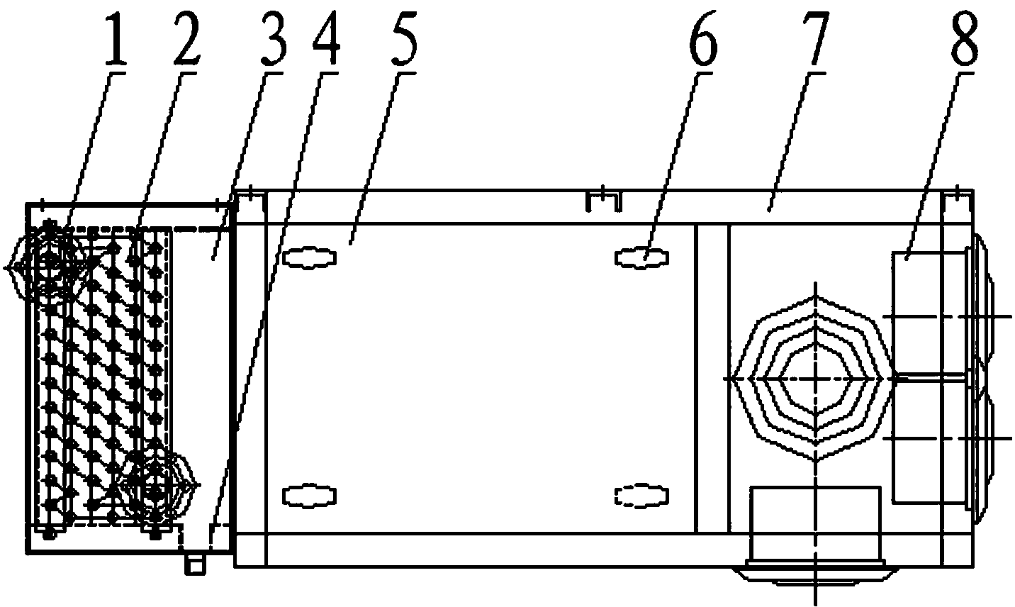
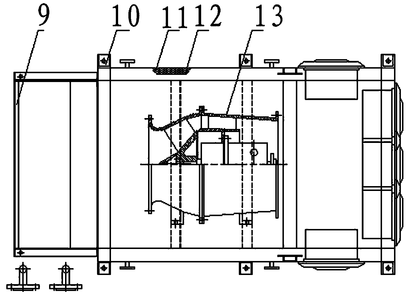
[0017] As shown in the figure, a marine jet-induced air-supply cooling device includes a box body 7 with lifting lugs 10, the outer wall of the box body is a sound-absorbing orifice plate 12, and the outer wall of the box body is also covered with heat-preserving and sound-absorbing materials 11 , the box body is provided with an inspection door panel 5, and a door lock 6 is arranged between the inspection door panel and the box body; the middle part of the box body is provided with a diagonal flow fan 13, and the air inlet of the diagonal flow fan 13 is provided with a cooling device, so The air inlet of the cooling device is provided with an air filter 9; the front, left, right, and lower faces of the front, left, right, and lower sides of the front end box 7 of the outlet of the oblique flow fan are provided with a plurality of jet ...


PUM


Abstract

The invention relates to a marine jet flow induced draught cooling device which comprises a box body, wherein a diagonal fan is arranged in the middle of the box body, a cooling device is arranged at the position of an air inlet of the diagonal fan, and jet flow nozzles are arranged on the front side, the left side, the right side and the lower side of the portion, in front of the air outlet portion of the diagonal fan, of the box body. Due to the fact that the jet flow nozzles are arranged on the left side, the right side and the lower side of the box body, the angle can be adjusted to enable air to be fed in all directions, and the air feeding range is wide.

Description

technical field [0001] The invention relates to the field of marine ventilation equipment, in particular to a marine jet flow induced air supply cooling device. Background technique [0002] With the global warming and the increase of equipment in the ship cabin, a large amount of heat emitted by the equipment is directly discharged into the cabin, causing the air temperature in the cabin to rise, which affects the accuracy and life of the equipment, so it is necessary to cool the cabin. Ship cabins originally used cooling equipment with large pressure head and high power, such as air conditioners to supply air for cooling through air ducts. Because there are many equipment in the cabin and they are not evenly distributed, there are structural girders and auxiliary beams on the top of the cabin, and the pipelines on the top There are so many cables, it is very difficult to arrange air ducts, and it is impossible to arrange air ducts in all positions, which is easy to ...

Claims


Application Information

Patent Timeline
Patent Type & Authority Applications(China)
IPC IPC(8): F24F5/00F24F13/06F24F13/065F24F13/062F24F13/24
Inventor 秦伯进陈兵刘鹏周海云蒋涛
Owner JIANGSU JOSUN AIR CONDITIONER
Why Eureka
Try Eureka