Optical sheet wheel, light source system and projection system

An optical sheet and runner technology, which is applied in the field of lighting and display, can solve the problem of heating of the filter 110 bracket, and achieve the effect of preventing breakage

Active Publication Date: 2016-08-10
峰米(北京)科技有限公司 +1
View PDF6 Cites 0 Cited by
  • Summary
  • Abstract
  • Description
  • Claims
  • Application Information

AI Technical Summary

Problems solved by technology

However, the optical filter 110 will absorb part of the light during the working process, or other working parts will generate heat so that the temperature near the filter wheel 100 is relatively high, thereby causing the optical filter 110 and the support of the rotating shaft 121 to be heated

Method used


Image

  • Optical sheet wheel, light source system and projection system
  • Optical sheet wheel, light source system and projection system
  • Optical sheet wheel, light source system and projection system

Examples


Embodiment 1

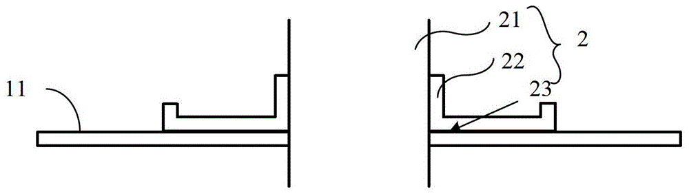
[0044] see Figure 2A , Figure 2A It is a structural schematic diagram of an embodiment of the optical sheet rotating wheel of the present invention. The optical sheet rotating wheel includes an optical device and a driving device 2 for driving the optical device to rotate.

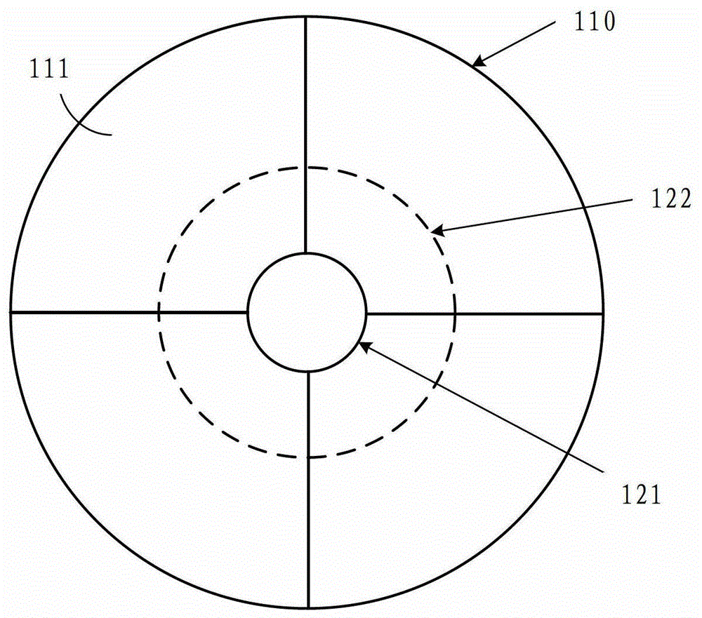
[0045] The optical device includes a circular optical sheet 11 . Such as Figure 2B as shown, Figure 2B yes Figure 2A Bottom view of the optical setup in the optical sheet wheel shown. In this embodiment, the optical sheet 11 is assembled by splicing four sub-optical sheets 11 a ringed on the rotation axis 21 and perpendicular to the rotation axis 21 . In this embodiment, the optical sheet 11 may include at least one of a filter, a diffuser, a light-transmitting sheet, and a reflective sheet, which are respectively used to filter, scatter, transmit, or reflect light beams. The optical sheet 11 is generally made of glass material. It is worth noting that the number of sub-optical sheets in the o...

Embodiment 2

[0068] In Embodiment 1, each sub-optical sheet in the optical sheet is directly bonded to the fixed surface to form a ring-shaped optical sheet. During the high-speed rotation of the optical sheet rotating wheel, the glue between each sub-optical sheet and the fixed surface provides centripetal force for each sub-optical sheet, so that the optical sheet rotates accordingly. The greater the rotational speed of the optical sheet wheel, the greater the centripetal force. However, since the optical sheet is not a complete whole, when the glue is not hard enough, each sub-optical sheet will fly out. This embodiment provides a solution to this problem.

[0069] see Figure 4 , Figure 4 It is a structural schematic diagram of another embodiment of the optical sheet rotating wheel of the present invention. The optical sheet rotating wheel includes an optical device 1 and a driving device 2 for driving the optical device 1 to rotate.

[0070] The difference between this embodimen...


PUM


Abstract

The embodiment of the invention discloses an optical sheet rotating wheel, a light source system and a projection system. The optical sheet rotating wheel includes a rotating shaft and a fixed surface fixed on the rotating shaft; The outer diameter of the optical sheet is larger than the outer diameter of the fixed surface; the fixed surface includes two hollow areas, and each hollow area is equipped with a dispensing area and a beam group, and each dispensing area only passes through the beam group and the non-hollowed out area. The areas are connected and fixed, and the beam group includes at least one beam; the optical device is fixed to the fixed surface only by bonding with the dispensing area; the stiffness of the beam group in each hollow area along the radial direction passing through the center of the dispensing area The coefficient is less than the first predetermined value, so that when the branch beam group is deformed under the predetermined temperature difference, the stress on the optical device along the radial direction through the dispensing area is less than or equal to the critical value, so that the stress on the optical device is less than the stress that causes it to break. Stress critical value. The invention can provide an optical sheet rotating wheel which prevents the optical sheet from being pulled.

Description

technical field [0001] The invention relates to the technical field of illumination and display, in particular to an optical sheet wheel, a light source system and a projection system. Background technique [0002] The function of the color wheel in the DLP (Digital Light Processing) projector is the separation and processing of colors, and the separation and filtering of colors by the color wheel needs to be realized through the high-speed operation of the color wheel. [0003] Disc-shaped filter wheels of the prior art such as Figure 1A and Figure 1B as shown, Figure 1A is a structural schematic diagram of a filter wheel in the prior art, Figure 1B yes Figure 1A Top view of the filter wheel shown. The filter wheel 100 includes a filter 110 and a driving device for driving the filter 110 to rotate. The driving device includes a rotating shaft 121 and a bracket 122 fixed on the rotating shaft. The bracket 122 is ring-shaped, and the ring is arranged on the rotating s...

Claims


Application Information

Patent Timeline
Patent Type & Authority Patents(China)
IPC IPC(8): G02B26/00G03B11/00G03B21/20G03B33/08
CPCG02B26/008F21S10/007G03B11/00G03B21/20G03B33/08
Inventor 叶红徐虎
Owner 峰米(北京)科技有限公司
Why Eureka
Try Eureka