Electronic devices with capacitive proximity sensors

A technology for proximity sensors and electronic equipment, which is applied to antenna equipment, electronic switches, circuits, etc. with additional functions, and can solve problems such as radio frequency transmission power limitation and implementation of antennas.

Active Publication Date: 2014-11-26
APPLE INC
View PDF7 Cites 27 Cited by
  • Summary
  • Abstract
  • Description
  • Claims
  • Application Information

AI Technical Summary

Problems solved by technology

This can make it difficult to implement antennas in electronic devices that contain conductive housing walls or other conductive structures that could block RF signals
Regulators may place limits on RF transmit power
These limitations pose challenges when operating electronic device antennas at elevated power levels

Method used


Image

  • Electronic devices with capacitive proximity sensors
  • Electronic devices with capacitive proximity sensors
  • Electronic devices with capacitive proximity sensors

Examples


Embodiment Construction

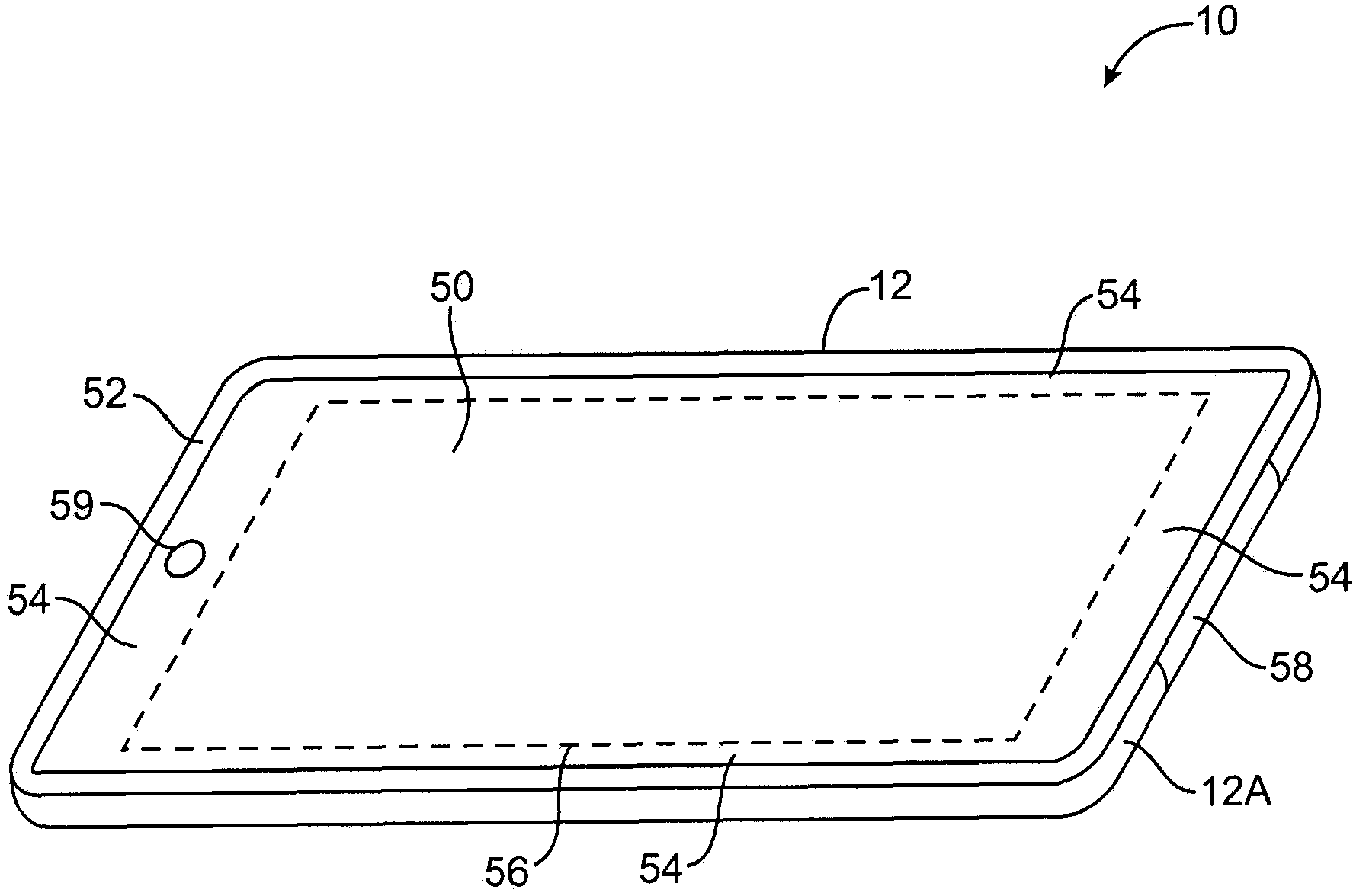
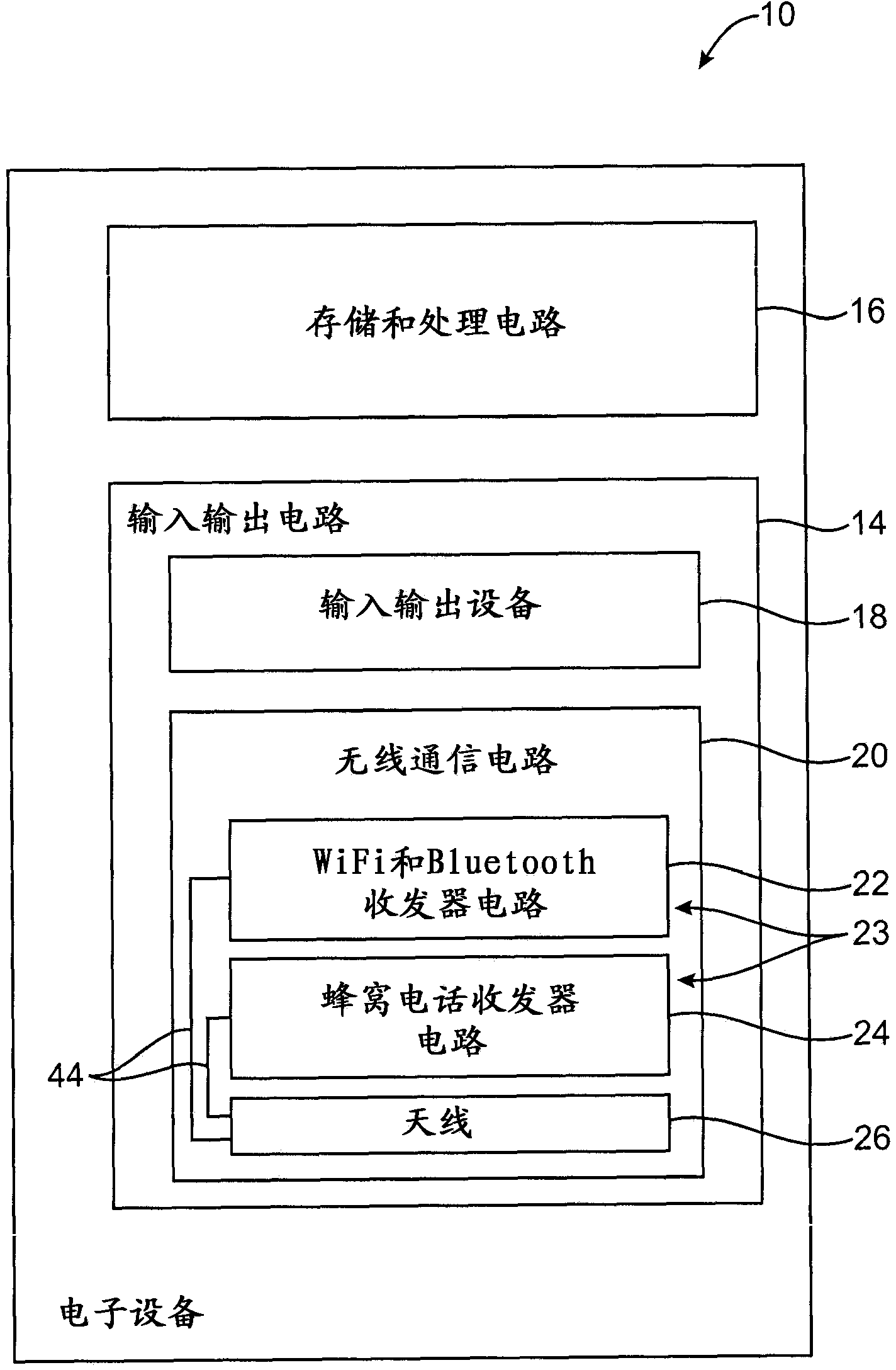
[0024] Electronic devices may be provided with wireless communication circuitry. Wireless communication circuitry may be used to support wireless communication in one or more wireless communication frequency bands. For example, wireless communication circuitry may transmit and receive signals in cellular telephone frequency bands.

[0025] To meet consumer demands for small form factor wireless devices, manufacturers are continually striving to reduce the size of the components used in these devices while providing enhanced functionality. Especially in configurations where electronic devices are used to transmit and receive radio frequency signals in cellular telephone bands and other communication bands with relatively wide bandwidths, meeting desired antenna performance standards in compact devices can be challenging. High transmit power and wide antenna bandwidth may be desirable in order to ensure adequate signal strength during communications, but these attributes may pr...


PUM


Abstract

An electronic device may have a housing in which an antenna is mounted. An antenna window may be mounted in the housing to allow radio-frequency signals to be transmitted from the antenna and to allow the antenna to receive radio-frequency signals. Near-field radiation limits may be satisfied by reducing transmit power when an external object is detected in the vicinity of the dielectric antenna window and the antenna. A capacitive proximity sensor may be used in detecting external objects in the vicinity of the antenna. The proximity sensor may have conductive layers separated by a dielectric. A capacitancc-to-digital converter may be coupled to the proximity sensor by inductors. The capacitive proximity sensor may be interposed between an antenna resonating element and the antenna window. The capacitive proximity sensor may serve as a parasitic antenna resonating element and may be coupled to the housing by a capacitor.

Description

[0001] This application is a divisional application of an invention patent application with an application date of July 9, 2010, an application number of 201010229675.5, and an invention title of "electronic equipment with a capacitive proximity sensor". [0002] This application claims priority to U.S. Provisional Patent Application No. 61 / 226,683, filed July 17, 2009, and U.S. Patent Application No. 12 / 632,695, filed December 7, 2009, the entire contents of which are hereby incorporated by reference . technical field [0003] The present invention relates generally to antennas, and more particularly to antennas for electronic devices. Background technique [0004] Electronic devices such as portable computers and handheld electronic devices are becoming increasingly popular. Devices such as these often have wireless communication capabilities. For example, an electronic device may use long-range wireless communication circuitry, such as cellular telephone circuitry, to c...

Claims


Application Information

Patent Timeline
Patent Type & Authority Applications(China)
IPC IPC(8): H01Q1/24H01Q1/44H03K17/955
CPCH01Q1/245H01Q1/243H03K17/955H01Q1/44H03K2217/960755H01Q1/24
Inventor D·T·安姆R·W·斯科卢巴O·S·勒格B·M·金李青湘E·A·瓦兹奎兹R·A·G·安古鲁蒋奕R·卡巴勒罗
Owner APPLE INC
Why Eureka
Try Eureka