Device for detecting acoustic signals and associated method

An acoustic signal and equipment technology, applied in the field of acoustic signal detection, can solve the problems of expensive signal filtering and unrealizable cost, and achieve the effect of simple processing and reduction of signal processing tasks.

Active Publication Date: 2017-02-22
ROBERT BOSCH GMBH
View PDF2 Cites 0 Cited by
  • Summary
  • Abstract
  • Description
  • Claims
  • Application Information

AI Technical Summary

Problems solved by technology

[0033] So in conclusion, with today's state of the art, according to the requirements discussed above, efficient filtering of signals is very expensive and hardly achievable with reasonable outlay

Method used


Image

  • Device for detecting acoustic signals and associated method
  • Device for detecting acoustic signals and associated method
  • Device for detecting acoustic signals and associated method

Examples


Embodiment Construction

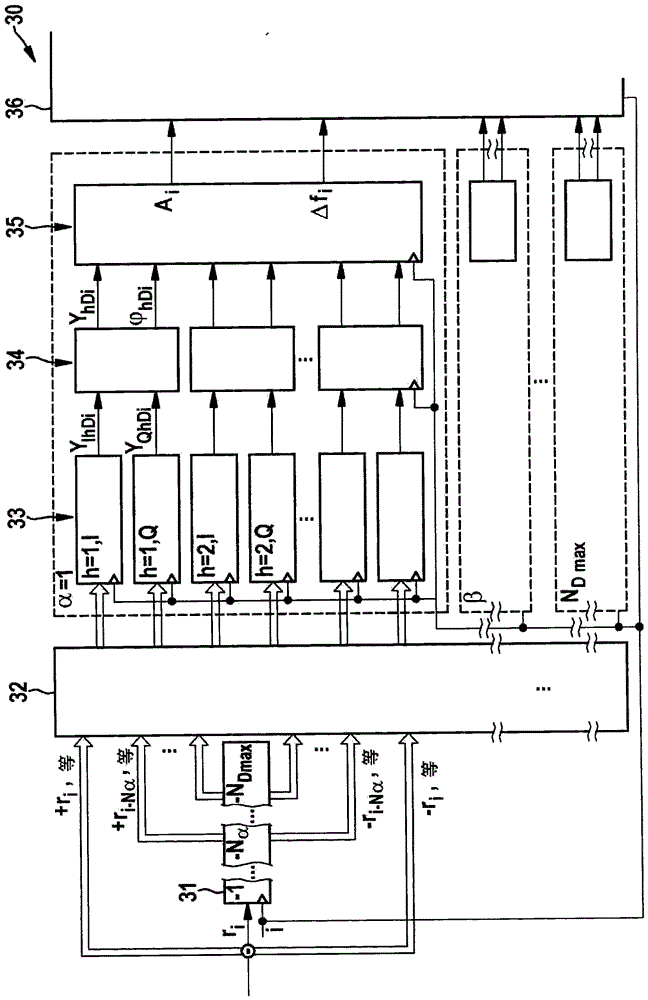
[0094] According to the first embodiment of the present invention ( image 3 As shown in ), the overall analysis processing architecture 30 consists of the following:

[0095] Delay-line module "Delay-Line" 31, which is used by the maximum delay N Dmax delay sample value r i and for the selected bit N of the delay line 31 D =N α ; N β ;...;N Dmax Delayed sampled values ​​are provided on and its negative values and their corresponding right-shifted variants when required;

[0096] A data pool 32 for forwarding previously provided data to a subsequent computing mechanism 33, said data pool being similar to a wiring network;

[0097] Calculation mechanism 33, which for each filter frequency f h and each filter bandwidth F·(N D +1) -1 The values ​​required in each calculation step and provided by the delay line 31 are placed on subsequent summing means by means of coefficient generators, so that their results are respectively used in subsequent in-phase y IhDi Or qua...


PUM


Abstract

Disclosed is a device for detecting an acoustic signal of a sound source, said device having a sampling device for time-discretized conversion of an incoming continuous signal, wherein said device has a delay line module and one or more Computing means, the delay line module receives sampled values ​​from the sampling device and is designed to simultaneously provide not only the sampled value ri applied to its input but also at least one delayed sampled value (I). The computing means each have a switching means acting as a coefficient generator, an adder / subtractor and a result memory controllable by means of the sampling clock i, the switching means being designed to be controlled according to the sampling clock i, whether the inversion is determined by The values ​​ri and / or (I) provided by the delay line module are either optionally added to the part of the calculated result yIhD(i-1) or yQhD(i-1) so far, directly or by right-shifting or Subtract the value from the portion. Furthermore, the relationship between the sampling frequency F and the filter frequency fh is preferably in accordance with the relationship: F=4·fh·(1; 2; 3; 4; . . . )±15%. Additionally, a method of belonging is provided.

Description

technical field [0001] The invention relates to a device and a method for detecting acoustic signals, in particular ultrasonic pulses, when detecting the surroundings of a vehicle. The invention finds application in particular in the detection of acoustic signals emitted by the host vehicle and / or by another point in the vehicle's surroundings and optionally reflected from objects in the vehicle's surroundings. Furthermore, a motor vehicle with a driver assistance system having a device according to the invention is provided. Background technique [0002] Today, for the acoustic surroundings detection of vehicles, ultrasonic systems with pulsed measurements are generally used, in which short signal pulses of the order of 0.3 milliseconds are emitted and the transitions of reflected waves on objects in the surroundings are performed according to the pulses. The distance to the object is determined over time using the speed of sound. When the sound source, the receiver and / o...

Claims


Application Information

Patent Timeline
Patent Type & Authority Patents(China)
IPC IPC(8): G01S15/93G01S7/527G01S7/533G01S15/931
CPCG01S7/5273G01S7/533G01S15/931G01S15/582G01S7/4065
Inventor M·卡尔
Owner ROBERT BOSCH GMBH
Why Eureka
Try Eureka