
High rate, long block length, low density parity check encoder

a parity check and encoder technology, applied in the field of encoders, can solve the problems of not providing optimized hardware and/or software implementations of algorithms for generating fecc codes, affecting the efficiency of coding, and not being reasonably practical in their implementation

Inactive Publication Date: 2011-09-13
HARRIS CORP
View PDF5 Cites 11 Cited by
  • Summary
  • Abstract
  • Description
  • Claims
  • Application Information

AI Technical Summary

Problems solved by technology

LDPC codes were not used at the time of their creation (i.e., 1960) because encoder and decoder implementations were not reasonably practical.
Despite the advantages of these approaches, they suffer from certain drawbacks.
For example, these approaches do not provide optimized hardware and / or software implementations of an algorithm for generating an FECC code.
This short block length is due to the complexity of the hardware implementation of the PEG algorithm.
Such conventional hardware implementations for LDPC encoders do not provide a practical means for handling block lengths in the range greater than about 10 kilo-bits.

Method used


Image

  • High rate, long block length, low density parity check encoder
  • High rate, long block length, low density parity check encoder
  • High rate, long block length, low density parity check encoder

Examples


example 1

[0106]Let m equal sixteen (16) and the desired total shift amount equal nine (9). In such a scenario, a u bit word is communicated from the ASC generator 110 (described above in relation to FIG. 1) to the register 418. The u bit world includes shift count information, More particularly, the u bit word is a binary representation of the desired total shift amount nine (9), As such, the u bit word is defined as a sequence 1 0 0 1. The register 418 communicates the first bit to the selector 402 and the remaining three (3) bits to the register 420. The first bit has a value of one (1). In effect, the selector 402 is transitioned into a first state. In this first state, the selector 402 circularly shifts each bit of an m bit word by eight (m / 2=16 / 2=8) positions. Subsequently, the selector 402 communicates the shifted m bit word to the register 404. In turn, the register 404 temporarily stores the shifted m bit word and communicates the shifted m bit word to the selector 406.

[0107]The regi...


PUM


Abstract

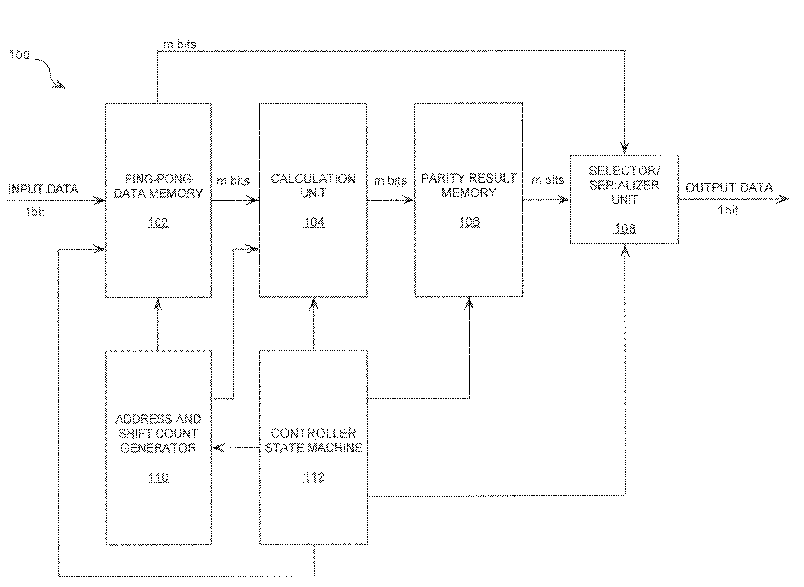
There is provided a parity check encoder (100) comprising a data memory (PPDM) configured for storing input data, a calculation / parity result data store (CPRDS), and a selector / serializer (SS). The CPRDS (104,106) is coupled to the PPDM (102) and is configured to calculate parity bits in parallel using input data and information contained in a parity check matrix H. The SS (108) is coupled to the PPDM and CPRDS. The SS is configured to generate an encoded output sequence using the input data and parity bits. The matrix H is formed of a plurality of sub-matrices. Each sub-matrix of the sub-matrices is an all zero (0) matrix, an identity matrix, or a circular right shifted version of the identity matrix. A portion B of the matrix H includes a plurality of rows having two (2) ones (1), except for a first row which includes a single one (1).

Description

BACKGROUND OF THE INVENTION[0001]1. Statement of the Technical Field[0002]The inventive arrangements relate to forward error correction code encoders. More particularly, the present invention relates to an encoder for Low Density Parity Check (LDPC) codes with particular structural features, allowing for long block lengths and high throughput rates.[0003]2. Description of the Related Art[0004]There are many types of forward error correction codes (FECCs) known in the art. One such type of FECC is a Low Density Parity Check (LDPC) code. A detailed description of LDPC codes can be found in “Low Density Party-Check Codes”, M.I.T. Press, 1963, written by Robert G. Gallager. The entire disclosure of this publication is incorporated herein by reference. An LDPC code can allow error free transmission of data across a channel at close to the theoretical limit of a channel capacity. LDPC codes were not used at the time of their creation (i.e., 1960) because encoder and decoder implementation...

Claims


Application Information

Patent Timeline
Patent Type & Authority Patents(United States)
IPC IPC(8): H03M13/00
CPCH03M13/11
Inventor OLAKER, DAVID A.SEGALLIS, GREG P.
Owner HARRIS CORP
Learn More