Method and device for improving heat exchange efficiency of fluid and die
A heat exchange efficiency and mold technology, applied in the field of mold temperature control, can solve the problems of reducing heat exchange capacity and pressure loss, and achieve the effects of improving production efficiency, sufficient heat exchange, and improving heat exchange efficiency
- Summary
- Abstract
- Description
- Claims
- Application Information
AI Technical Summary
Problems solved by technology
Method used
Image

Examples
Embodiment 1
[0022] The specific conditions of the method for improving the heat exchange efficiency between fluid and mold described in this embodiment are as follows:
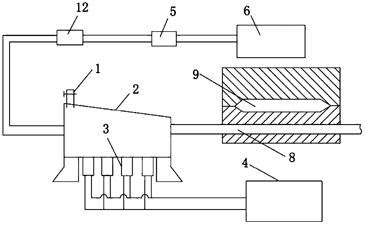
[0023] First, the fluid that will flow into the cooling / heating channel of the mold is first introduced into the ultrasonic container with exhaust valve; secondly, the ultrasonic transducer is controlled by the ultrasonic generator to apply ultrasonic waves to the fluid in the ultrasonic container, so that the The fluid generates ultrasonic vibration and transmits it to the cooling / heating channel of the mold; finally, the fluid oscillates violently in the cooling / heating channel, greatly improving the heat exchange efficiency between it and the mold, thereby realizing rapid cooling or heating of the mold.
[0024] like figure 1 As shown, in order to realize the device of the above-mentioned method of the present embodiment, it includes an ultrasonic container 2 with an exhaust valve 1, an ultrasonic transducer 3, and an ...
Embodiment 2
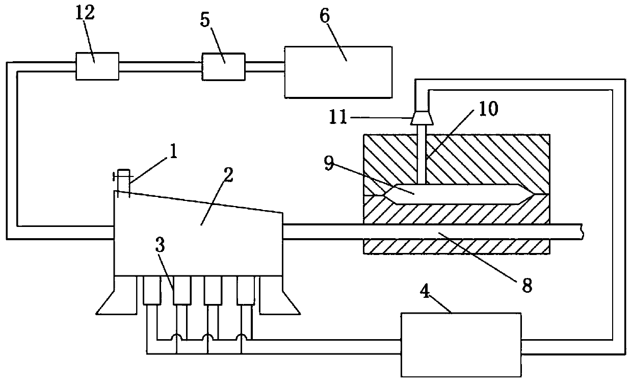
[0027] like figure 2 As shown, the difference from Embodiment 1 is that a vibration rod 10 extends into the cavity 9 of the mold in this embodiment, and another ultrasonic transducer 11 is fixed on the vibration rod 10. The energy device 11 is electrically connected with the ultrasonic generator 4, and the ultrasonic generator 4 controls the application of ultrasonic waves to the vibrating rod 10, so that the vibrating rod 10 generates ultrasonic vibration with the same frequency as the fluid flowing through the cooling / heating channel 8 in the mold. , to achieve ultrasonic vibration on the material in the mold cavity, and finally the two ultrasonic waves act on the mold to resonate, further improving the heat exchange efficiency between the fluid and the mold.
Embodiment 3
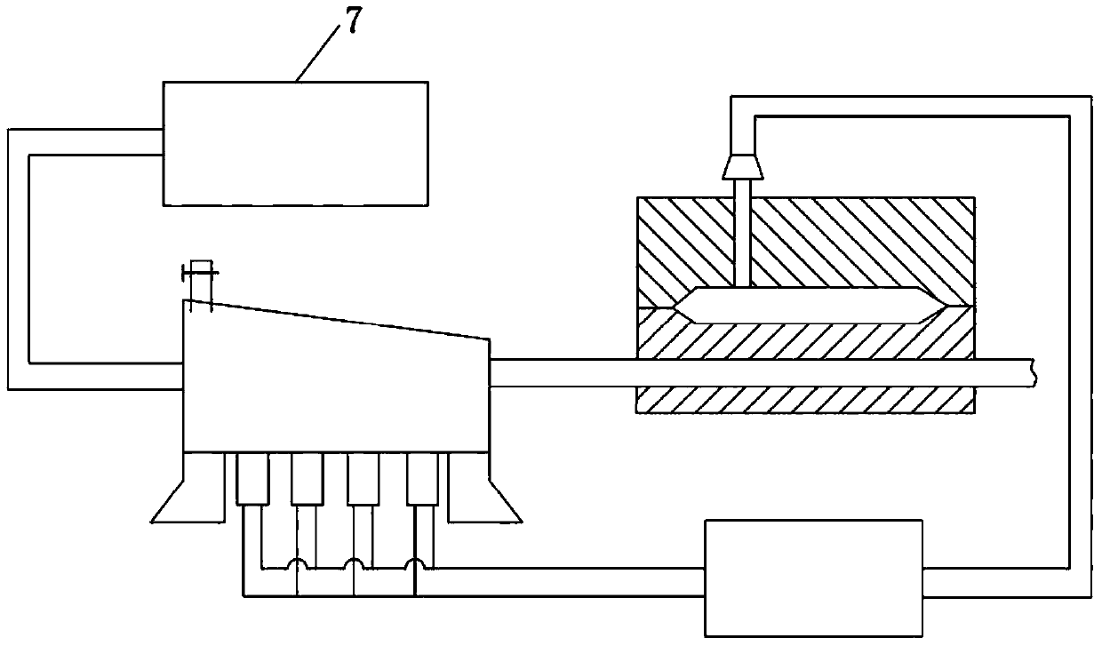
[0029] like image 3 As shown, what is different from Embodiment 1 is that the fluid inlet of the ultrasonic container 2 in this embodiment is connected to the mold temperature machine 7 through a pipeline, the material to be formed in the cavity 9 of the mold is magnesium alloy, and the mold temperature machine 7 makes the temperature high The mould is heated as the oil at mould temperature flows through the cooling / heating channels 8 in the mould.
PUM
 Abstract
Description
Claims
Application Information
 - Generate Ideas
- Intellectual Property
- Life Sciences
- Materials
- Tech Scout
- Unparalleled Data Quality
- Higher Quality Content
- 60% Fewer Hallucinations
Browse by: Latest US Patents, China's latest patents, Technical Efficacy Thesaurus, Application Domain, Technology Topic, Popular Technical Reports.
© 2025 PatSnap. All rights reserved.Legal|Privacy policy|Modern Slavery Act Transparency Statement|Sitemap|About US| Contact US: help@patsnap.com