Gaugeable container

A container and container can technology, which is applied in the field of milk powder cans and utensil devices with a measuring mechanism, can solve the problems of complex operation, unsanitary, pollution, etc., and achieve the effect of simple and accurate reclaiming process and reducing the risk of contamination.

Inactive Publication Date: 2014-12-03
两化(宁波)科技有限公司
View PDF6 Cites 2 Cited by
  • Summary
  • Abstract
  • Description
  • Claims
  • Application Information

AI Technical Summary

Problems solved by technology

[0002] Simple measuring devices for measuring liquids or powders generally include special measuring tools such as measuring cylinders, measuring cups, measuring bottles, and measuring spoons. The method of using such measuring tools is to manually pour liquid or powder from one device to another by the operator. The operator needs to have certain skills, otherwise it is easy to pour the liquid or powder out of the container, it is difficult to control the pouring amount of the liquid or powder, the operation is complicated and cannot be quickly measured, resulting in inaccurate measurement; at the same time, the entire pouring process is not in a closed It is carried out in an environment where the liquid or powder is in contact with the outside world, which can easily cause pollution
With the improvement of people's quality of life, milk powder has become a universal nutritious food in people's lives. However, after people have scooped up the milk powder with a spoon, they usually put the spoon back into the milk powder jar. It is very unhygienic to use it, and the milk powder spoons currently used do not have a measuring function, and people can only scoop milk powder according to actual experience

Method used


Image

  • Gaugeable container
  • Gaugeable container
  • Gaugeable container

Examples


Embodiment Construction

[0023] The specific implementation manner of the present invention will be described below in conjunction with the accompanying drawings.

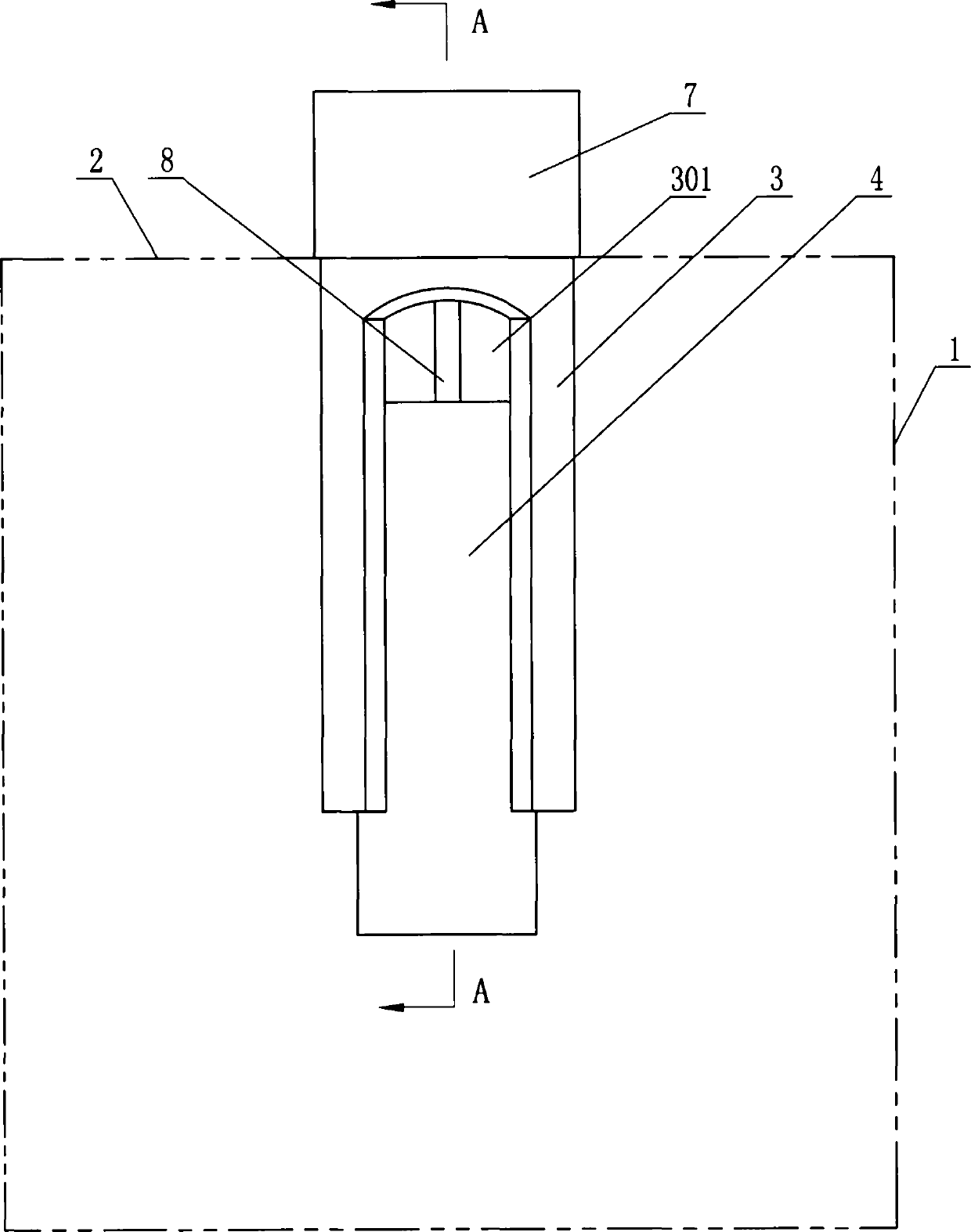
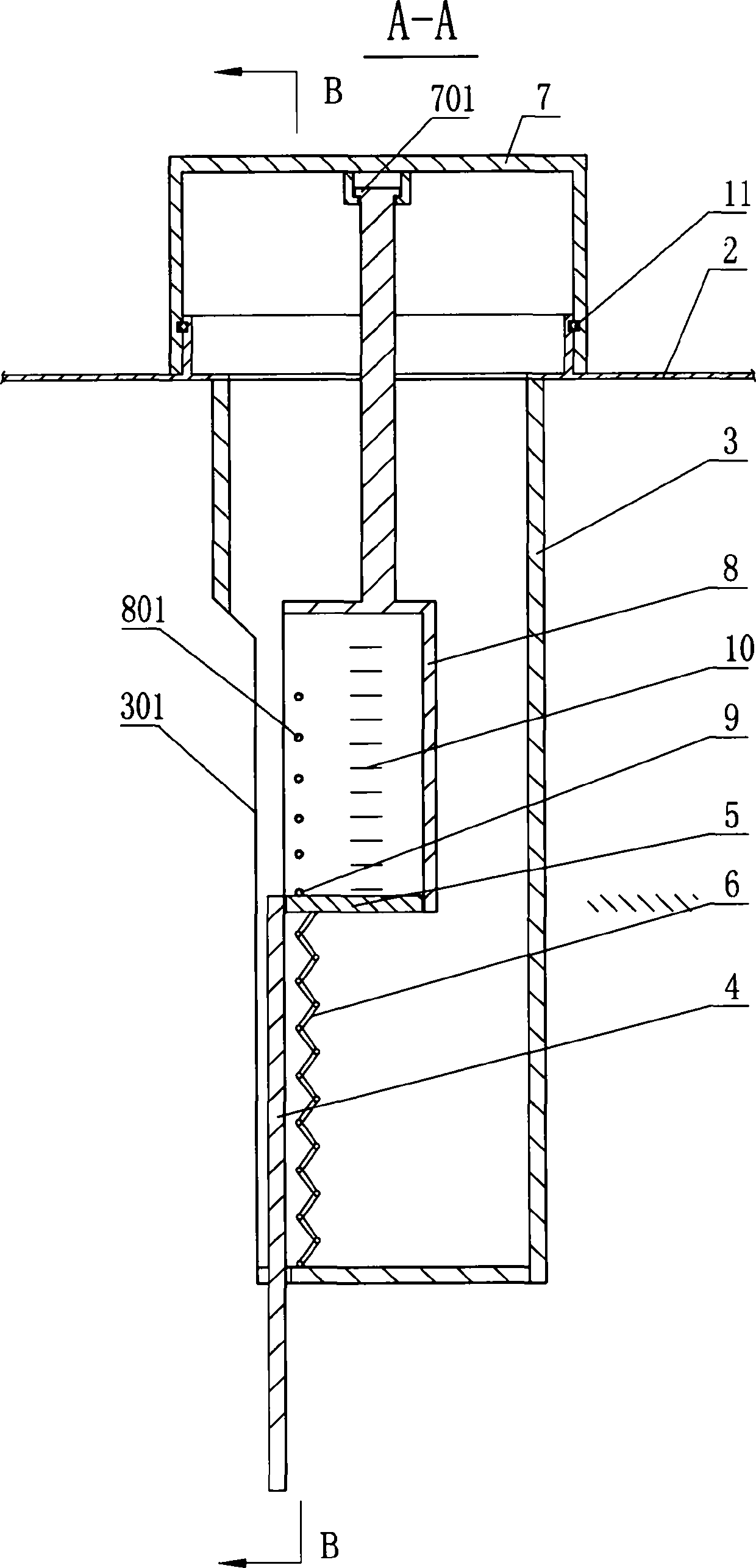
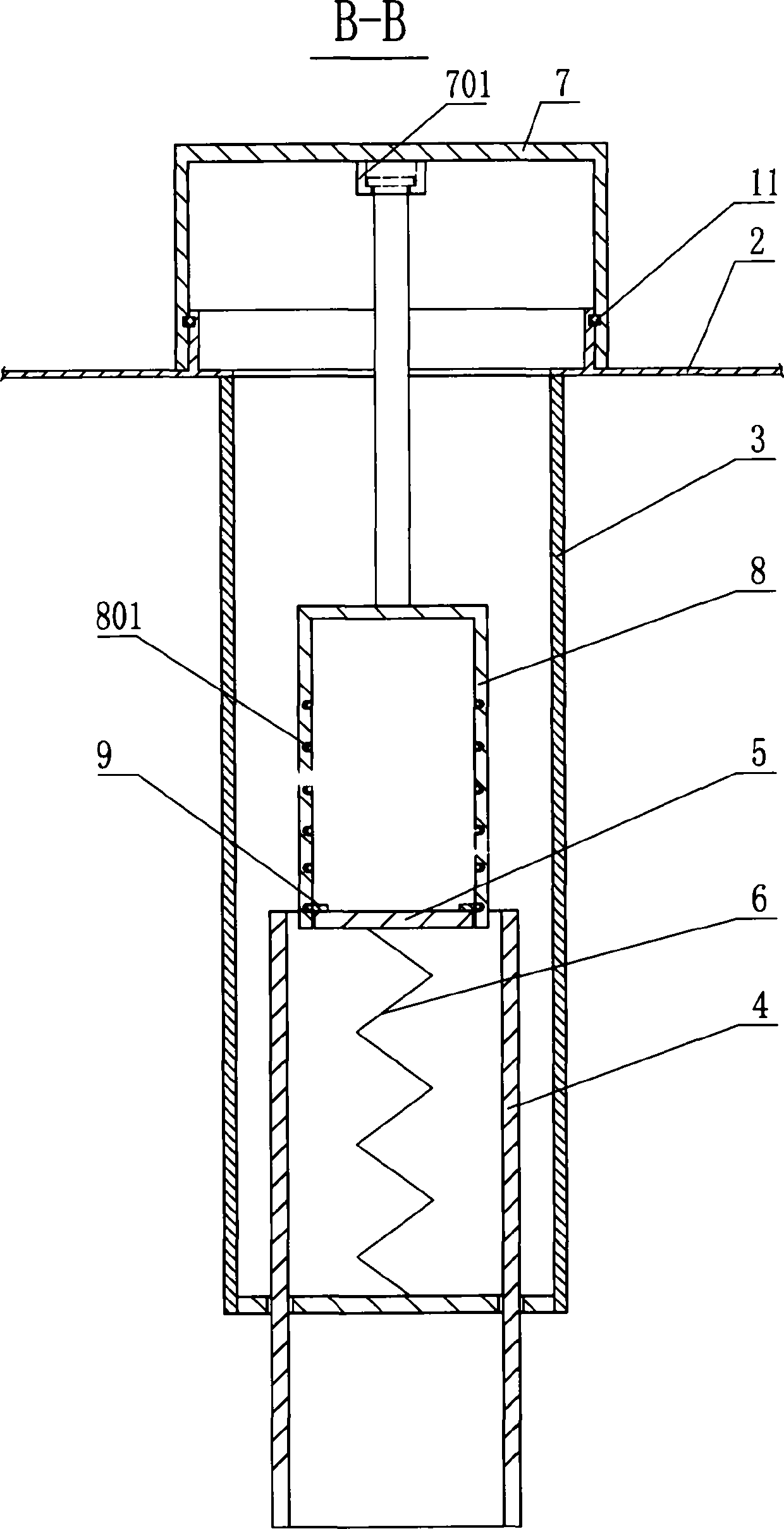
[0024] See figure 1 , figure 2 , image 3 , the present invention includes a tank body 1 and a tank cover 2 that closes or closes the opening of the tank body 1, the tank cover 2 is provided with a through axial opening, the metering bottle body 3 is integrally formed with the tank cover 2 and is integrated with the The axial opening communicates, the metering bottle body 3 is located in the tank body 1, and the axis of the metering bottle body 3 is parallel to the axis line of the tank body 1, and the wall of the metering bottle body 3 has a material inlet and outlet 301 extending in the axial direction. The material inlet and outlet 301 communicates with the interior of the tank body 1. A slide cover 4 is slidably connected to the material inlet and outlet 301. The slide cover 4 is used to open or close the material inlet and outlet 3...


PUM


Abstract

A gaugeable container comprises a tank body and a tank cover, wherein an axial opening runs through the tank cover; a measuring bottle body and the tank cover are integrally formed, and the measuring bottle body is communicated with the axial opening; the measuring bottle body is positioned in the tank body; a material inlet / outlet extending in the axial direction is formed in the bottle wall of the measuring bottle body and communicated with the interior of the tank body; a sliding cover is connected onto the material inlet / outlet in a sliding manner and used for opening or closing the material inlet / outlet; a baffle is arranged at the upper end of the sliding cover; a spring is arranged between the baffle and the bottom of the measuring bottle body; the periphery of the axial opening of the tank cover is in hermetical threaded connection with a bottle cap; the inner side of the cover cap is connected with a measuring spoon capable of rotating relatively; the spoon body of the measuring spoon is communicated with the material inlet / outlet and extends in the axial direction of the measuring bottle body; a pushing part is fixedly connected with the inner side of the spoon body of the measuring spoon; the pushing part is propped against the upper end face of the baffle; the baffle extends into the measuring spoon in the radial direction; the wall surface of the outer circumference of the baffle is propped against the wall surface of the inner circumference of the spoon body of the measuring spoon. The gaugeable container is convenient to meter, clean and sanitary, and has a measuring function.

Description

technical field [0001] The invention relates to the field of container devices, in particular to a container device with a metering mechanism, and in particular to a milk powder container with a meterable mechanism arranged on the lid of the milk powder container. Background technique [0002] Simple measuring devices for measuring liquids or powders generally include special measuring tools such as measuring cylinders, measuring cups, measuring bottles, and measuring spoons. The method of using such measuring tools is to manually pour liquid or powder from one device to another by the operator. The operator needs to have certain skills, otherwise it is easy to pour the liquid or powder out of the container, it is difficult to control the pouring amount of the liquid or powder, the operation is complicated and cannot be quickly measured, resulting in inaccurate measurement; at the same time, the entire pouring process is not in a closed It is carried out in an environment wh...

Claims


Application Information

Patent Timeline
Patent Type & Authority Applications(China)
IPC IPC(8): B65D83/06
Inventor 韩鹏超
Owner 两化(宁波)科技有限公司
Why Eureka
Try Eureka