
Transmitting device and plasma machining equipment

A transmission device and processing technology, applied in the directions of transportation and packaging, conveyor objects, etc., can solve the problems of short transmission distance of the mechanical arm, unable to meet the transmission distance requirements, etc., and achieve the effect of simple structure, easy control and simplified structure

Inactive Publication Date: 2014-12-03
BEIJING NAURA MICROELECTRONICS EQUIP CO LTD
View PDF7 Cites 9 Cited by
  • Summary
  • Abstract
  • Description
  • Claims
  • Application Information

AI Technical Summary

Problems solved by technology

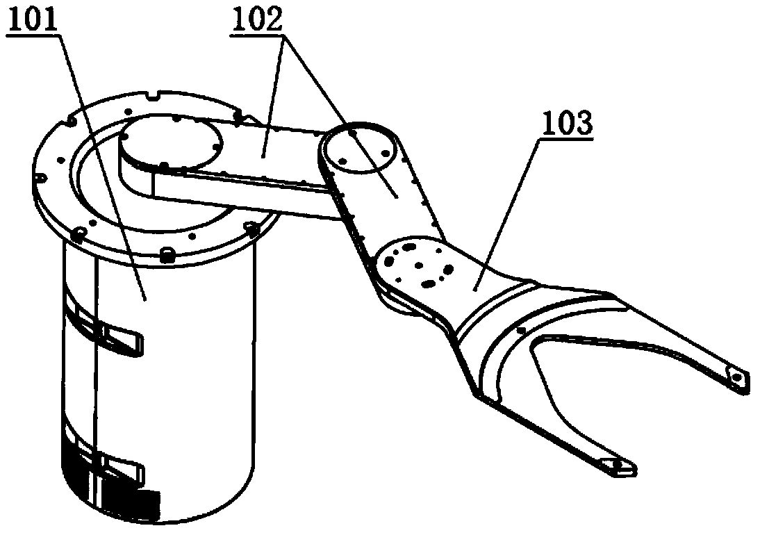
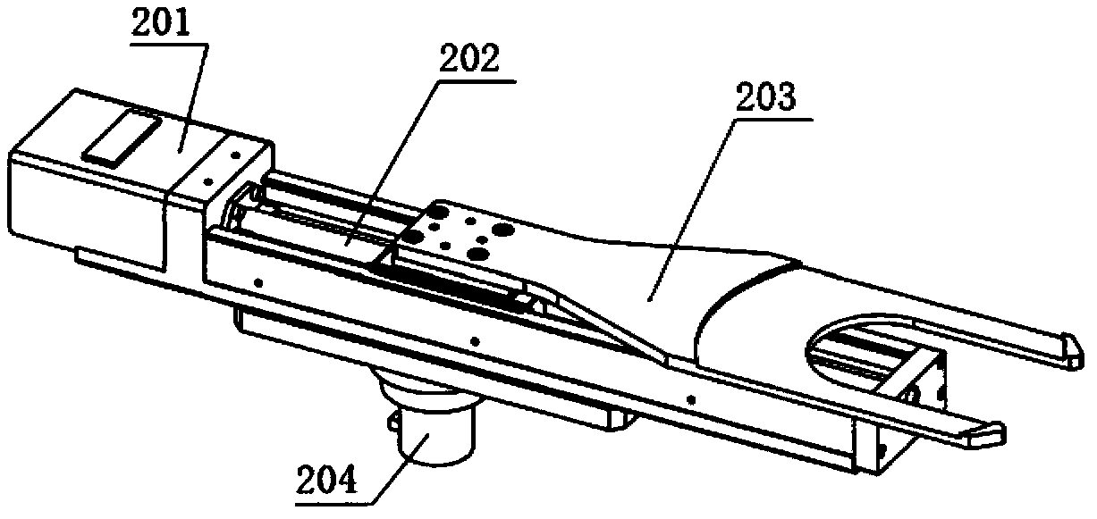
[0009] Although the structure of the above-mentioned mechanical arm is simple, easy to control and low in cost, due to the limitation of the overall length of the mechanical arm, the maximum movable stroke of the grasping part 203 is the length of the screw 202 in its axial direction, resulting in mechanical The transmission distance of the arm is short, so it may not be able to meet the occasions that require high transmission distance

Method used


Image

  • Transmitting device and plasma machining equipment
  • Transmitting device and plasma machining equipment
  • Transmitting device and plasma machining equipment

Examples


Embodiment Construction

[0034] In order for those skilled in the art to better understand the technical solution of the present invention, the transmission device and the plasma processing equipment provided by the present invention will be described in detail below with reference to the accompanying drawings.

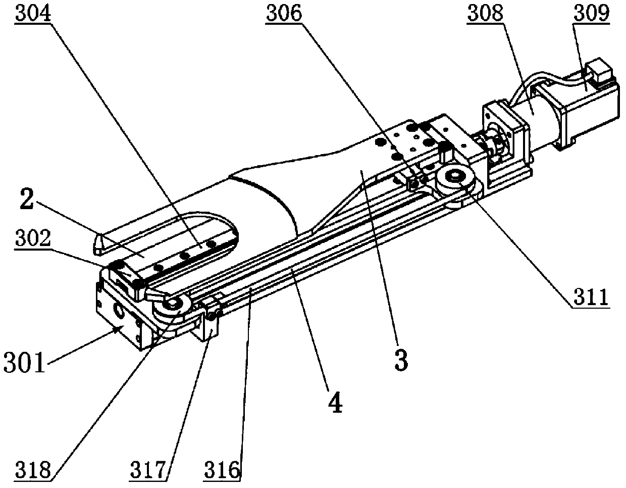
[0035] image 3 It is a perspective view of the transmission device provided by the first embodiment of the present invention. Figure 4 It is a cross-sectional view of the transmission device provided by the first embodiment of the present invention. Please also refer to image 3 with Figure 4 , the transmission device includes a linear drive unit, a fixed part 2, a gripping part 3 and an indirect transmission mechanism 4. Wherein, the linear drive unit is used to drive the fixed component 2 to perform linear reciprocating motion. In this embodiment, the linear drive unit includes a housing 301 , a rotating motor 309 , a lead screw 11 and a second sliding member 12 . Wherein, the lead s...


PUM


Abstract

The invention provides a transmitting device and plasma machining equipment. The transmitting device is used for transmitting a machined workpiece and comprises a linear driving unit, a fixing part, a grasping part and an indirect transmission mechanism, wherein the linear driving unit is used for driving the fixing part on the linear driving unit to make linear reciprocating motion; the grasping part is positioned on the fixing part and is relatively slidably connected with the fixing part; the grasping part is used for grasping the machined workpiece; the indirect transmission mechanism is arranged on the fixing part and is used for synchronously driving the grasping part to slide relative to the fixing part when the fixing part is driven to make linear reciprocating motion by the linear driving unit, and the sliding direction of the grasping part relative to the fixing part is the same as the moving direction of the fixing part. The transmitting device provided by the invention has the advantages of simple structure, easiness in control, lower manufacturing cost and larger transmitting distance.

Description

technical field [0001] The invention relates to the technical field of microelectronic processing, in particular to a transmission device and plasma processing equipment. Background technique [0002] In the manufacturing process of semiconductors, LED chips, liquid crystal displays, etc., it is necessary to gradually transfer workpieces such as wafers or substrates from the atmosphere to a vacuum reaction chamber for processing, and then transfer them out of the reaction chamber after the process is completed. This process requires a set of transmission system consisting of transmission device, vacuum equipment and testing equipment, etc., the most important of which is the transmission device, which is an automatic mechanical arm that can carry the workpiece in the atmosphere or vacuum environment, so it is also Often referred to as a transfer manipulator or robot. [0003] When transferring the workpiece to be processed, it is usually hoped that the transmission device u...

Claims


Application Information

Patent Timeline
Patent Type & Authority Applications(China)
IPC IPC(8): B65G47/90
Inventor 张鹏
Owner BEIJING NAURA MICROELECTRONICS EQUIP CO LTD
Learn More