
Anti-floating pressure-relief drainage system

A pressure relief and pressure relief well technology, applied in protection devices, buildings, infrastructure engineering, etc., can solve the problems of corresponding changes in force, shorten the service life of underground structures, waste resources, etc., to avoid deformation and maintain anti-floating stability. performance, ensuring normal service life

Inactive Publication Date: 2014-12-03
SOUTHWESTERN ARCHITECTURAL DESIGN INST
View PDF4 Cites 11 Cited by
  • Summary
  • Abstract
  • Description
  • Claims
  • Application Information

AI Technical Summary

Problems solved by technology

[0004] However, during the use of underground buildings, traditional anti-floating devices cannot predict the change of groundwater level and the force is difficult to change accordingly with the change of groundwater level, so that the anti-floating device has no buoyancy effect most of the time, resulting in virtual waste of resources, or Excessive buoyancy in the later use will cause the anti-floating device to fail, resulting in deformation, cracking, water seepage or more serious accidents in the basement, shortening the service life of the underground structure

Method used


Image

  • Anti-floating pressure-relief drainage system
  • Anti-floating pressure-relief drainage system

Examples


Embodiment Construction

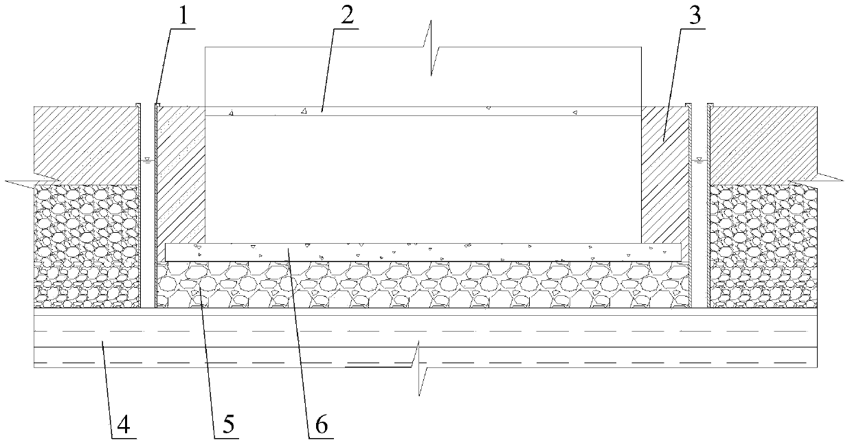
[0021] The core of the present invention is to provide a drainage, pressure relief and anti-floating system, which can effectively prevent the failure of the anti-floating device during its life cycle, thereby affecting the service life of the underground structure.

[0022] In order to enable those skilled in the art to better understand the technical solutions of the present invention, the present invention will be further described in detail below in conjunction with the accompanying drawings and embodiments.

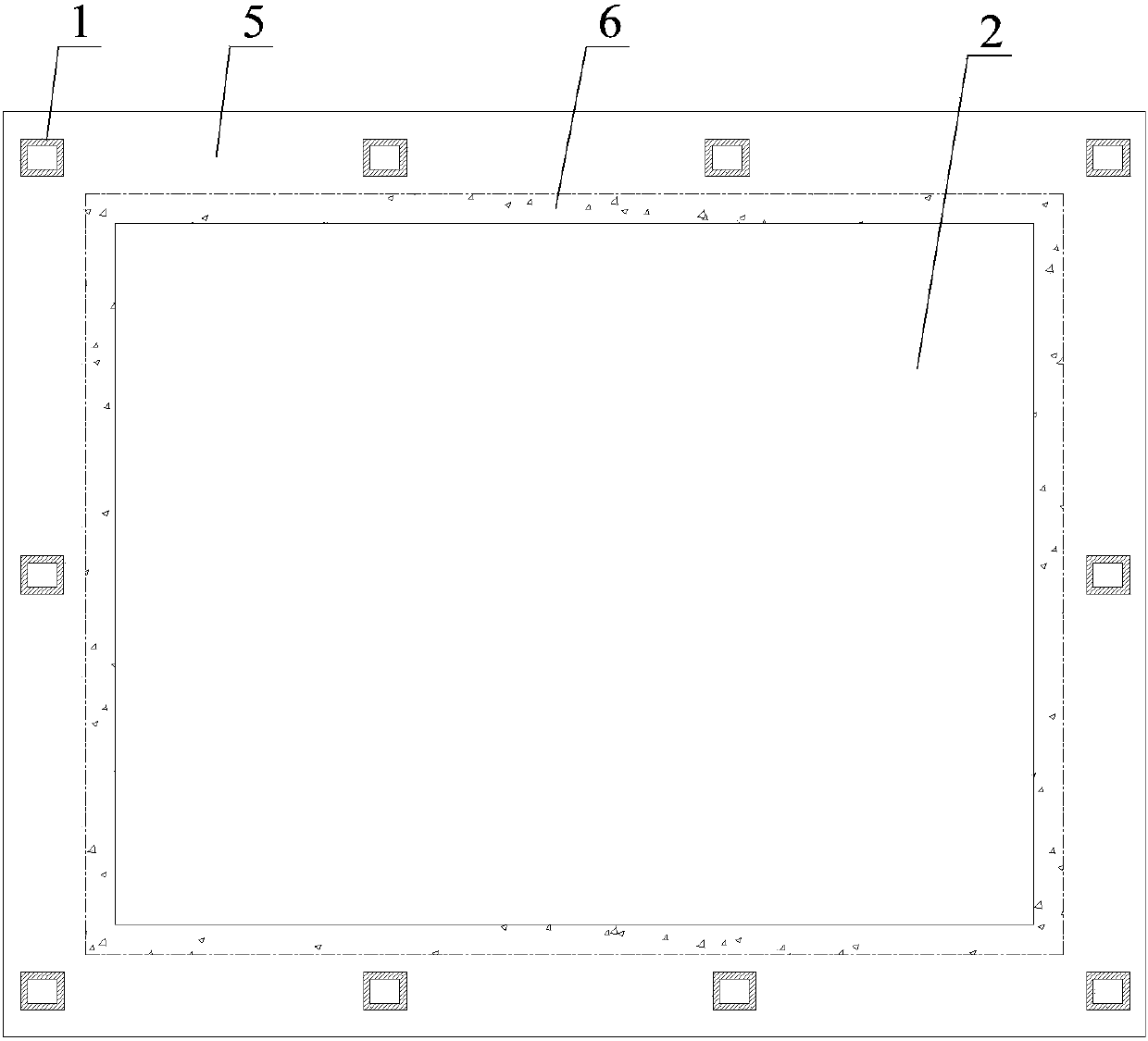
[0023] Please refer to Figure 1 to Figure 2 , in a specific embodiment, the drainage, pressure relief and anti-floating system provided by the present invention includes a bedrock layer 4, a foundation plate 6, a foundation permeable layer 5, a basement outer filling layer 3, a relief well 1 and a pumping device, and the basement The outer filling layer 3 and the foundation permeable layer 5 are juxtaposed above the bedrock layer 4, the foundation permeable layer 5 ...


PUM


Abstract

The invention discloses an anti-floating pressure-relief drainage system comprising a bedrock layer, a base board and a ground water permeable layer. The ground water permeable layer is located above the bedrock layer. The system further comprises a pressure-relief well communicated with the ground water permeable layer and a draining device used for draining underground water in the wall and relieving the pressure, and the pressure-relief well is located on the outer side of the base board. Since the pressure-relief well is mounted outside the base board, the situation of floating produced by a system body can be acquired by observing the level changes in the pressure-relief well; when the level in the pressure-relief well is higher than that of floating that the base board is capable of bearing, the underground water in the pressure-relief well can be drained timely through the draining device, the situations that the water difference between the building underground structure bottom and the side wall is large and an anti-floating device is in failure in the life cycle are avoided effectively, the anti-floating stability of the underground structure is retained, the situation of underground structure deformation, cracking and water penetrating caused by water pressure difference are avoided effectively, the normal service life of the underground structure is guaranteed.

Description

technical field [0001] The invention relates to the technical field of building construction, in particular to a drainage, pressure relief and anti-floating system. Background technique [0002] With the continuous progress of the social economy, the population is increasing, and the above-ground space is becoming more and more urgent, so more and more buildings are developing to the underground space. [0003] With the continuous deepening of underground structures, the problem of anti-floating has gradually become prominent. The traditional method is to solve the problem of anti-floating of underground buildings by setting anti-floating devices such as anti-floating anchor rods or anti-floating piles. [0004] However, during the use of underground buildings, traditional anti-floating devices cannot predict the change of groundwater level and the force is difficult to change accordingly with the change of groundwater level, so that the anti-floating device has no buoyancy ...

Claims


Application Information

Patent Timeline
Patent Type & Authority Applications(China)
IPC IPC(8): E02D31/12
Inventor 康景文周其健于远辉杜超胡熠许凡郑立宁
Owner SOUTHWESTERN ARCHITECTURAL DESIGN INST
Learn More