

Camshaft phasers and their rotors and variable cam timing systems
A phase adjuster and camshaft technology, which is applied to machines/engines, engine components, mechanical equipment, etc., can solve the problems of large axial size of the rotor, high rotor manufacturing cost, complicated rotor manufacturing process, etc., to simplify the manufacturing process, The effect of reducing the axial dimension and reducing the manufacturing cost
- Summary
- Abstract
- Description
- Claims
- Application Information
AI Technical Summary
Problems solved by technology
Method used
Image

Examples
no. 1 example
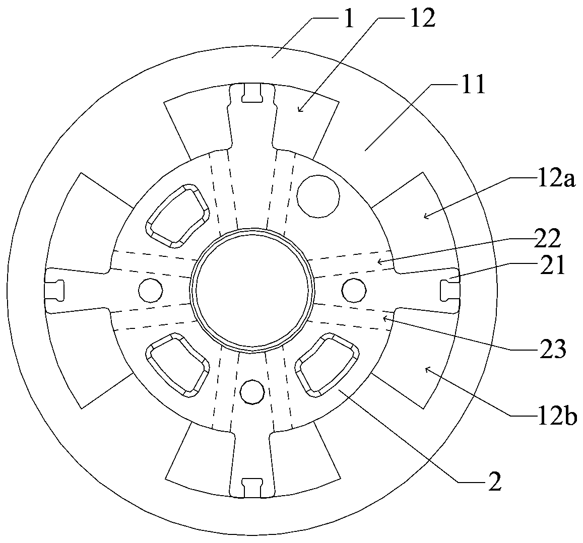
[0054] Such as Figure 5 and Figure 6 As shown, the variable cam timing system provided by the present invention includes: a camshaft phase adjuster, which includes a rotor 100 and a stator 200. The first groove 111 ; the camshaft 700 , which has an end accommodated in the first groove 111 of the rotor 100 , is connected in a rotationally fixed manner to the camshaft phaser.
[0055] In this embodiment, the camshaft phase adjuster further includes: a front cover 300 and a rear cover 400 , and the front cover 300 and the rear cover 400 are respectively fixed on the front and rear sides of the stator 200 . In a specific embodiment, a plurality of bolts 500 can be used to fix the front cover 300 , the rear cover 400 and the stator 200 together. The front cover 300 is in contact with the front end of the rotor 100 , and the rear cover 400 is in contact with the rear end of the rotor 100 .
[0056] In this example, if Figure 6 As shown, the camshaft 700 also includes a shaft ho...
no. 2 example
[0091] In the second embodiment, as Figure 14 As shown, the first oil groove 112 of the rotor 100 runs through the groove wall (not marked) of the first groove 111, so that the first oil groove 112 directly communicates with the first groove 111; the number of the second groove 113 is the same as that of the second oil groove 121 The number is equal, all the first oil grooves 112 and the second grooves 113 are arranged in a staggered manner, and the bottom of each second groove 113 and the second oil groove 121 exposes the axial through hole 130, so that each second oil groove 121 passes through the axial The through hole 130 communicates with a second groove 113 .
[0092] When the rotor of the second embodiment of the present invention is applied to the camshaft phase adjuster, in one working state of the camshaft phase adjuster, continue referring to Figure 14 As shown, the engine oil can directly flow to the first oil groove 112, and then flow into the first pressure ch...
no. 3 example
[0097] The following improvements can also be made to the rotor of the first embodiment to obtain the rotor of the third embodiment (not shown). The difference between the rotor of the third embodiment and the rotor of the first embodiment is that: the first oil groove of the rotor runs through the groove wall of the first groove, so that the first oil groove directly communicates with the first groove; The number is one, the second groove and all the first oil grooves are arranged at intervals, and a third groove is provided on the front surface of the base body, and the bottom of the third groove and the second groove exposes the axial through hole, and all the second grooves The oil groove is located on the periphery of the third groove and communicates with the third groove, and the second oil groove communicates with the axial through hole through the third groove.
[0098] In this case, in order to enable the camshaft of the first embodiment to be used in cooperation wit...
PUM
 Abstract
Description
Claims
Application Information