
Automatic centering control device and centering method thereof

An automatic centering and adjusting device technology, which is applied to wind turbine components, engines, wind power generation, etc., can solve problems such as high maintenance costs, great manpower and material resources, damage to gearboxes and generators, etc., to achieve Ease of implementation, simple structure, and convenient installation

Active Publication Date: 2014-12-03
JIANGSU NEW UNITED HEAVY IND SCI & TECH +1
View PDF6 Cites 13 Cited by
  • Summary
  • Abstract
  • Description
  • Claims
  • Application Information

AI Technical Summary

Problems solved by technology

While the wind power industry is developing vigorously, the safety of wind turbines is getting more and more attention. Frequent damage to the gearbox and generator has brought great losses to the owner. Once the gearbox or generator is damaged , maintenance will consume a lot of manpower and material resources
The main reason for the damage of the gearbox and the generator is that the shafts of the two are not aligned. The elastic support used by the generator of the wind turbine is generally a rubber product. With the increase of the service life, the elastic support gradually becomes aging and invalid, making The centering performance between the gearbox and the generator drops sharply, resulting in additional load and vibration during the operation of the gearbox and the generator, resulting in damage to the gearbox and the generator, and frequent manual alignment adjustments The maintenance cost is too high and it is very difficult to implement

Method used


Image

  • Automatic centering control device and centering method thereof
  • Automatic centering control device and centering method thereof
  • Automatic centering control device and centering method thereof

Examples


Embodiment Construction

[0018] The present invention is described in further detail now in conjunction with accompanying drawing. These drawings are all simplified schematic diagrams, which only illustrate the basic structure of the present invention in a schematic manner, so they only show the configurations related to the present invention.

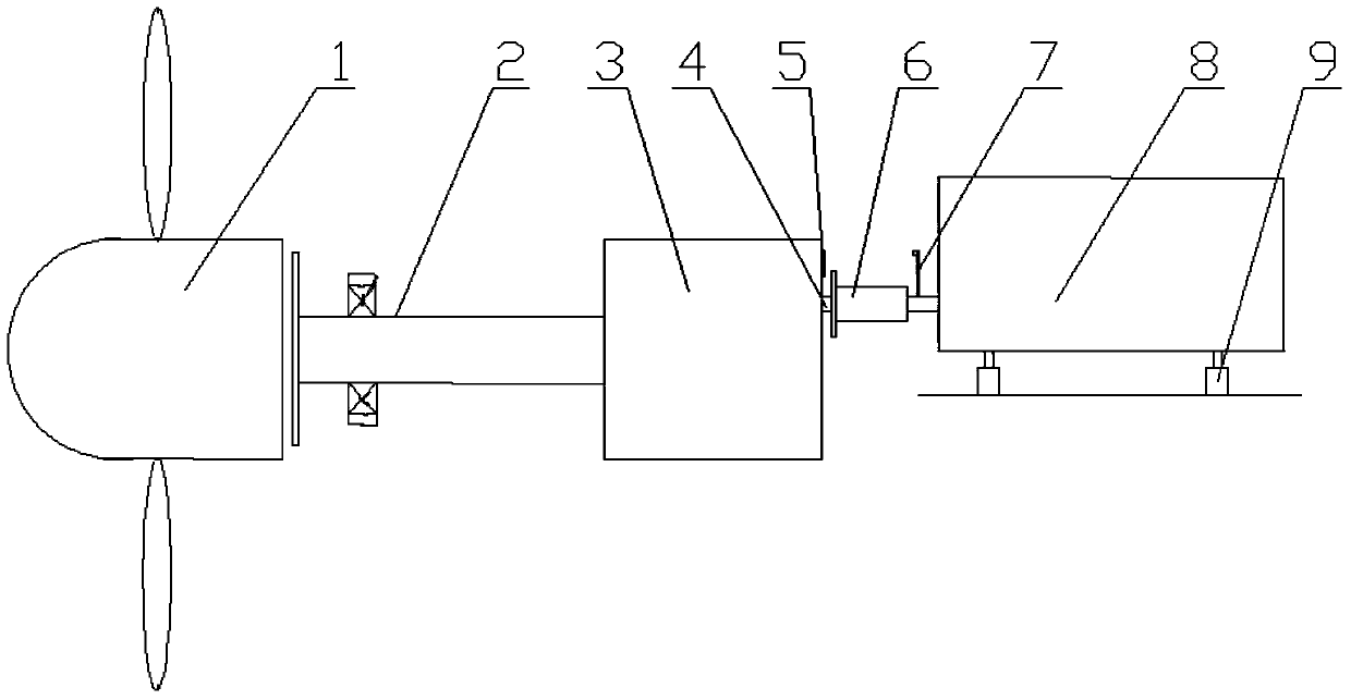
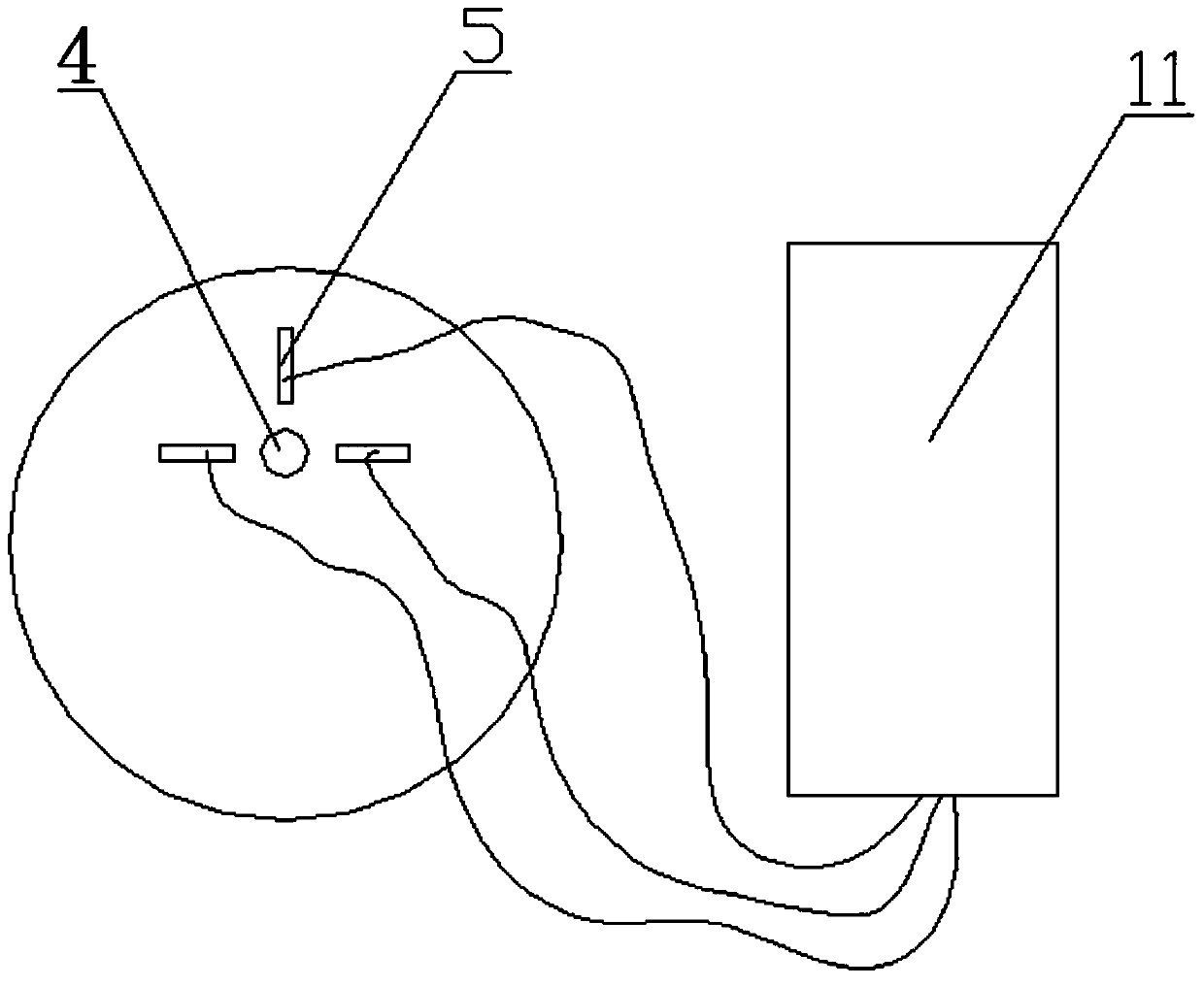
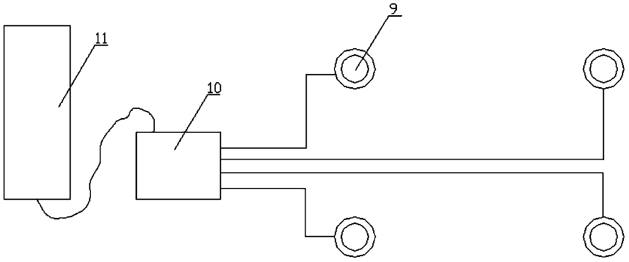
[0019] Such as Figure 1~3 As shown, the present invention provides an automatic centering adjustment device used between the gearbox and the generator, which is installed in the wind turbine, and the wind turbine includes an impeller 1, a main shaft 2, a gearbox 3, and a coupling 6 and the generator 8, one end of the main shaft 2 is fixedly connected with the impeller 1, and the other end is connected with the speed-up box 3, and the output shaft 4 of the speed-up box 3 is connected with the input shaft of the generator 8 through a coupling 6, which includes three A grating sensor 5, a laser emitting device 7, four hydraulic leveling supports 9, a hydrau...


PUM


Abstract

The invention provides an automatic centering control device used between a speed increasing box and a power generator. The automatic centering control device used between the speed increasing box and the power generator comprises three grating sensors, a laser emission device, a plurality of hydraulic pressure leveling supports, a hydraulic station and a main controller, wherein the three grating sensors are mounted on the speed increasing box and are in communication connection with the main controller; the distances between grating sensors and an output shaft are the same; the laser emission device is fixedly connected with the input shaft of the power generator; the plurality of hydraulic pressure leveling supports are connected with the hydraulic station and are supported at the bottom of the power generator; the hydraulic station is in communication connection with the main controller. The automatic centering control device and the centering method thereof, provided by the invention, are simple in structure; through regulating the heights of the hydraulic pressure leveling supports in real time, the centering is conducted; the automatic centering control device and the centering method thereof ensures that the coaxiality of the speed increasing box and the coaxiality of the power generator are in an ideal range; therefore, the normal operation of the speed increasing box and the normal operation of the power generator are ensured; the speed increasing box and the power generator are prevented from damages caused by the decline of the coaxiality.

Description

technical field [0001] The invention relates to the technical field of wind power generation, in particular to an automatic centering adjustment device and a centering method used between a gearbox and a generator. Background technique [0002] As a clean and renewable energy, wind energy is sought after by countries all over the world. While the wind power industry is developing vigorously, the safety of wind turbines is getting more and more attention. Frequent damage to the gearbox and generator has brought great losses to the owner. Once the gearbox or generator is damaged , Maintenance will consume a lot of manpower and material resources. The main reason for the damage of the gearbox and the generator is that the shafts of the two are not aligned. The elastic support used by the generator of the wind turbine is generally a rubber product. With the increase of the service life, the elastic support gradually becomes aging and invalid, making The centering performance...

Claims


Application Information

Patent Timeline
Patent Type & Authority Applications(China)
IPC IPC(8): F03D11/00F03D11/04
CPCY02E10/72Y02E10/728
Inventor 查俊张琳
Owner JIANGSU NEW UNITED HEAVY IND SCI & TECH
Learn More