Micro-bubble pipeline flowing drag reduction method and micro-bubble drag-reduced pipeline

A micro-bubble and pipeline technology, applied in the direction of fluid flow, pipe/pipe joint/pipe fitting, pipe element, etc., can solve the problem of large frictional resistance, and achieve the effect of improving drag reduction rate, reducing frictional resistance and increasing fluid velocity

Active Publication Date: 2014-12-03
SUZHOU QISHUO INFORMATION TECH CO LTD
View PDF2 Cites 6 Cited by
  • Summary
  • Abstract
  • Description
  • Claims
  • Application Information

AI Technical Summary

Problems solved by technology

[0005] The technical problem to be solved by the present invention is: to overcome the deficiencies of the prior art, to provide a drag reduction method for micro-bubbl...

Method used


Image

  • Micro-bubble pipeline flowing drag reduction method and micro-bubble drag-reduced pipeline
  • Micro-bubble pipeline flowing drag reduction method and micro-bubble drag-reduced pipeline
  • Micro-bubble pipeline flowing drag reduction method and micro-bubble drag-reduced pipeline

Examples


Embodiment 1

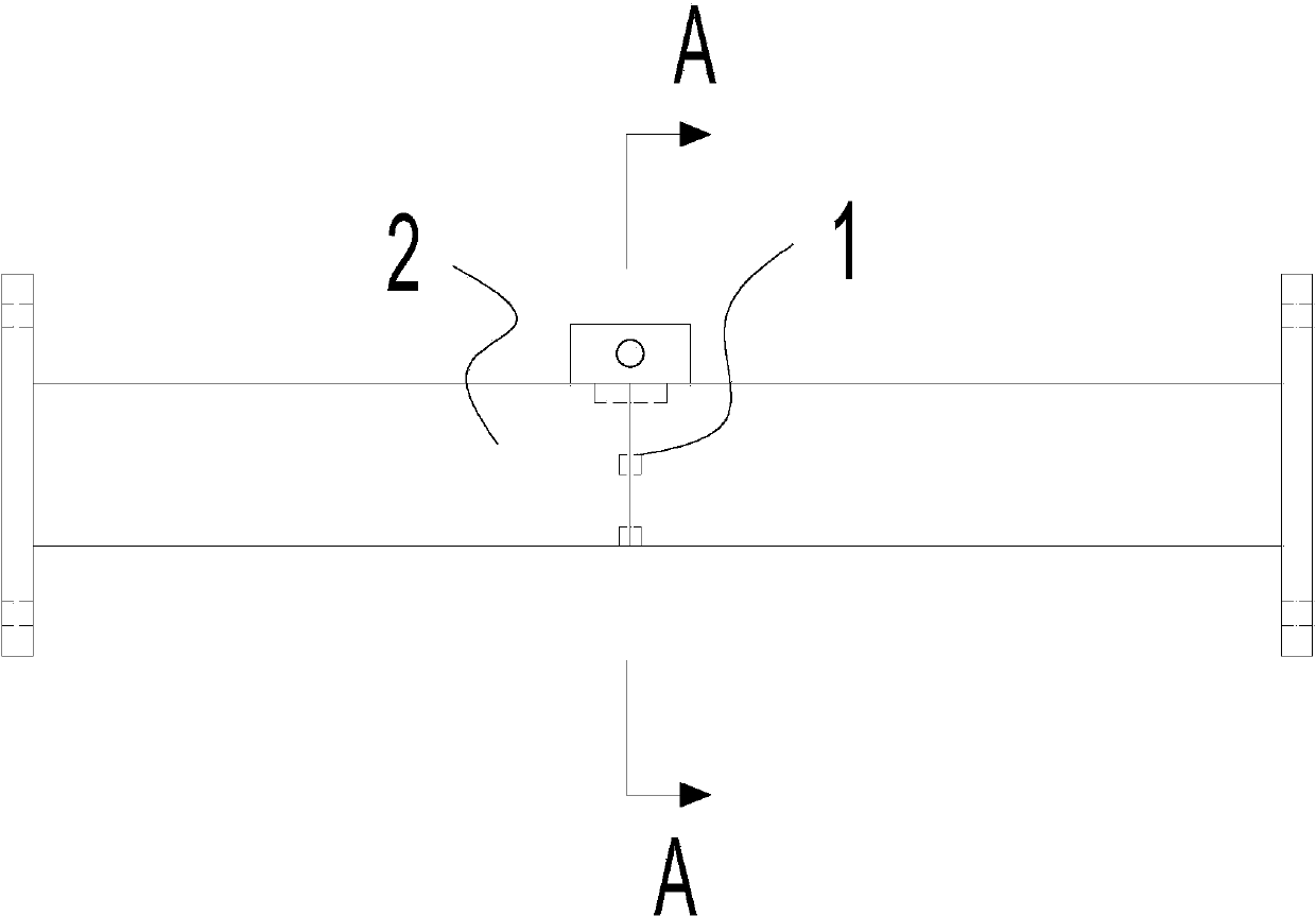
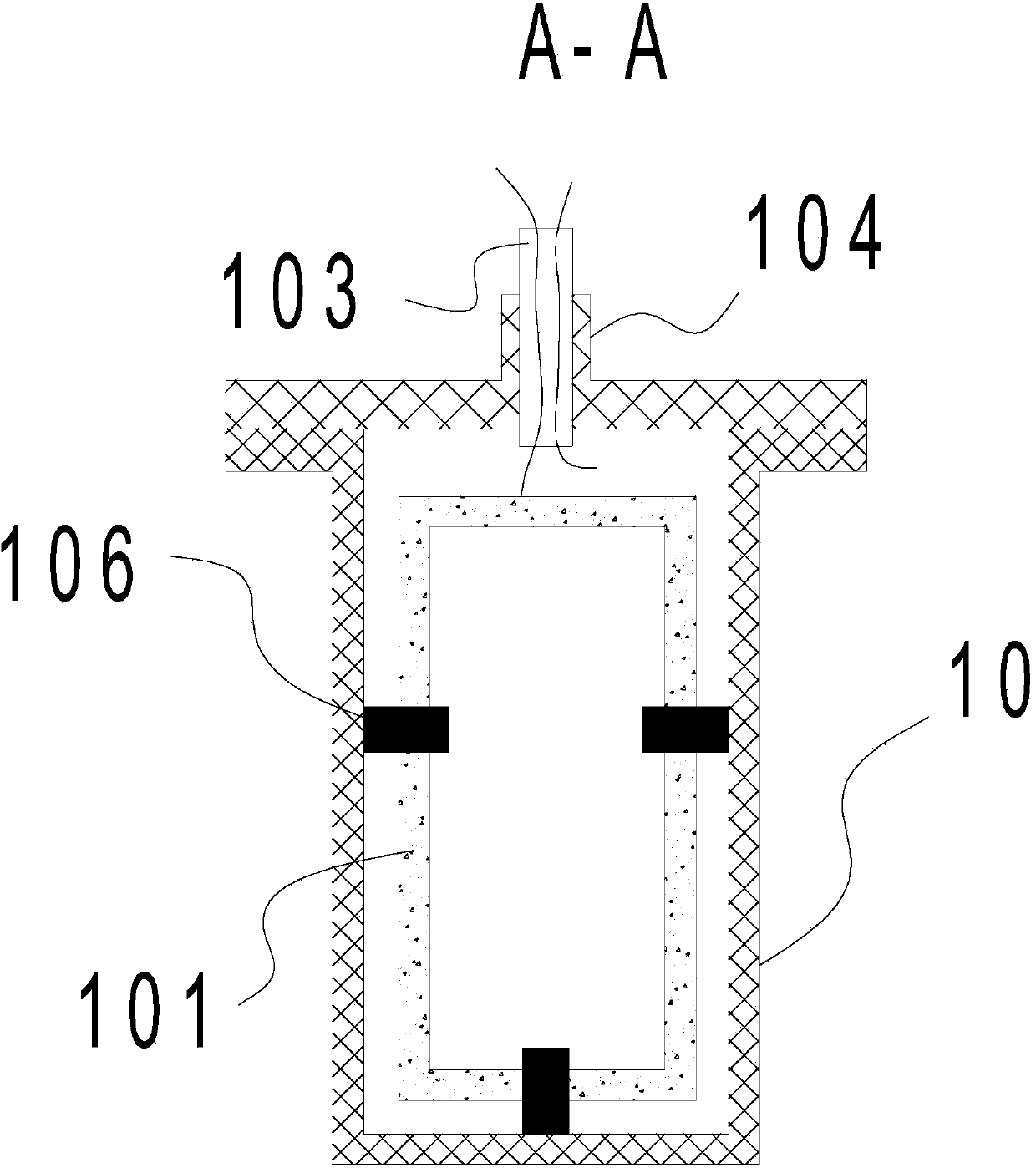
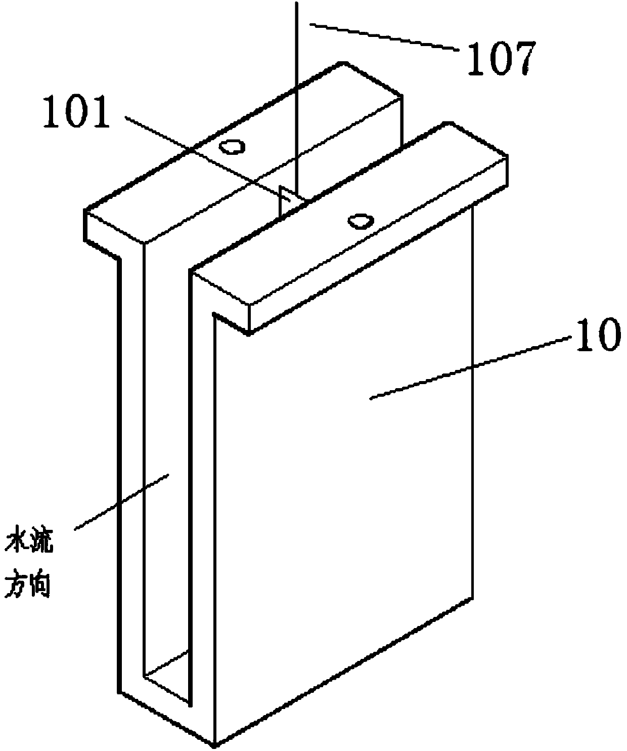
[0032] Embodiment 1; as Figure 1 to Figure 6 As shown, a microbubble drag-reducing pipeline includes a pipe body 2, the cross section of the pipe body 2 is a rectangular structure, and the two ends of the pipe body 2 are respectively provided with an inlet port and an outlet port. Connection, the inlet end and the outlet end of the rectangular pipe body 2 are respectively provided with a connecting flange 3, which facilitates the connection of the drag reducing pipeline of the present invention with other pipelines; the pipeline of the pipe body 2 is provided with A two-dimensional channel 10, the two ends of the two-dimensional channel 10 are respectively sealed and connected to the rectangular pipe body 2, and an electrolytic ring 101 is arranged in the two-dimensional channel 10. The electrolytic ring 101 has a rectangular frame structure, and the electrolytic ring 101 is fixed Set in the transition layer area in the two-dimensional channel 10 , the wire 107 of the electro...

Embodiment 2

[0037] Embodiment 2: as Figure 7 Figure 8 As shown, a micro-bubble drag reduction pipeline includes a pipe body 2, the cross section of which is a circular structure, and the two ends of the circular pipe body 2 are respectively provided with an inlet port and an outlet port. There is an electrolysis ring 101, which is in the shape of a ring, and the electrolysis ring 101 is fixedly arranged in the transition layer area in the circular tube body 2, and the wire of the electrolysis ring 101 extends out of the circular tube body 2 to connect to the power supply.

[0038] Three baffles 106 for fixing the electrolytic ring 101 are arranged on the inner wall of the circular tube body 2. The electrolytic ring 101 is fixed in the circular tube body 2 through the baffle plate 106, and the electrolytic ring can be fixed through the baffle plate 106. 101 is more stably fixed in the pipe body 2, avoiding changing its position due to the impact of water flow.

[0039] In order to faci...


PUM


Abstract

The invention relates to a micro-bubble pipeline drag reduction method. Micro-bubbles are directly generated in a transition layer of a turbulent flow field in a pipeline through electrolysis by an electrolytic ring, the micro-bubbles interact with turbulent flows in the transition layer of the flow field, turbulent flow fluctuation is inhibited, and flowing turbulent flow drag reduction is realized. A micro-bubble drag-reduced pipeline comprises a pipeline body, wherein the section of the pipeline body adopts a rectangular structure, a two-dimensional groove channel is formed in the pipeline of the pipeline body, two ends of the two-dimensional groove channel are connected with the rectangular pipeline body respectively in a sealed manner, the electrolytic ring is arranged in the two-dimensional groove channel and adopts a rectangular frame structure, the electrolytic ring is fixedly arranged in a transition layer area in the two-dimensional groove channel, and a lead of the electrolytic ring extends out of the two-dimensional groove channel to be connected with a power supply. By the aid of interaction of the micro-bubbles and the turbulent flows in the transition layer, the turbulent flow fluctuation is inhibited, the flowing turbulent flow drag reduction is realized, the frictional drag in a liquid pipeline delivery process is reduced, the drag reduction efficiency is improved, unnecessary waste is reduced, and the delivery speed of a fluid is increased as far as possible under the same micro-bubble air quantity.

Description

technical field [0001] The invention relates to the technical field of turbulent flow drag reduction in liquid pipelines, in particular to a flow drag reduction method for microbubble pipelines and a microbubble drag reduction pipeline. Background technique [0002] Energy shortage is one of the important issues restricting sustainable economic development and threatening human progress, so energy conservation and emission reduction have become the focus of social attention. When the fluid is transported by pipeline, the loss caused by the frictional resistance between the fluid and the wall is a major part of the energy loss, so reducing the frictional resistance in the process of fluid transport is an important form of energy saving. Although various drag reduction technologies such as surfactant drag reduction, coating drag reduction, rib drag reduction, plasma drag reduction, and wall suction drag reduction have been developed, these drag reduction methods are difficult ...

Claims


Application Information

Patent Timeline
IPC IPC(8): F15D1/06F16L55/02
Inventor 庞明军徐一丹袁惠新
Owner SUZHOU QISHUO INFORMATION TECH CO LTD
Why Eureka
Try Eureka