Electric locking and unlocking mechanism

A technology of unlocking mechanism and kinematic mechanism, applied in the direction of mechanical equipment, fixing devices, etc., can solve problems such as installation space limitation, potential safety hazards, locking and unlocking structures that cannot be qualified

Active Publication Date: 2014-12-03
HUBEI SANJIANG AEROSPACE HONGFENG CONTROL
View PDF5 Cites 8 Cited by
  • Summary
  • Abstract
  • Description
  • Claims
  • Application Information

AI Technical Summary

Problems solved by technology

[0002] According to the needs of product research and development, the locking and releasing functions of the official products of the display system are completed by the compression release device, and the compression release device is an pyrotechnic product. Multiple test verifications, each time using pyrotechnics for testing, will bring safety hazards and increase test costs
When testing the deployment time of the display system, the signal must be accurately collected, and the size of the original compression release device is relatively small, and the replacement product is limited by the installation space. The general locking and unlocking structure cannot become a qualified test replacement product

Method used


Image

  • Electric locking and unlocking mechanism
  • Electric locking and unlocking mechanism
  • Electric locking and unlocking mechanism

Examples


Embodiment Construction

[0021] In order to make the object, technical solution and advantages of the present invention clearer, the present invention will be further described in detail below in conjunction with the accompanying drawings and embodiments. It should be understood that the specific embodiments described here are only used to explain the present invention, not to limit the present invention. In addition, the technical features involved in the various embodiments of the present invention described below can be combined with each other as long as they do not constitute a conflict with each other.

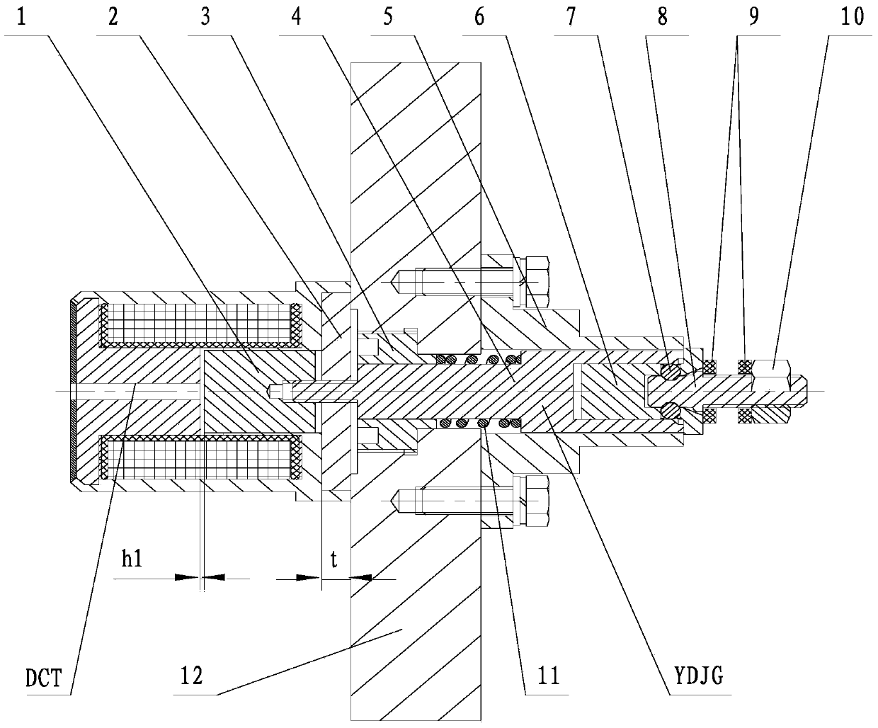
[0022] Refer to attached figure 1 , the electric locking and unlocking mechanism provided by the present invention is mainly composed of DC electromagnet DCT, kinematic mechanism YDJG, spring 11, threaded pressure block 3 and unfolding test plate 12, etc., wherein kinematic mechanism YDJG is composed of guide sleeve bracket 5, sliding sleeve 4. The ball rack 6, the locking ball 7, the locking b...


PUM


Abstract

The invention discloses an electric locking and unlocking mechanism which comprises a direct-current electromagnet, a moving mechanism, a spring, a threaded pressing block and an unfolded test plate. The moving mechanism and the direct-current electromagnet are mounted on two parallel and opposite sides of the unfolded test plate provided with a through hole through a guide sleeve respectively, a sliding sleeve is in threaded connection with an armature of the direct-current electromagnet on the other side through the through hole of the unfolded test plate, and the sliding sleeve is coaxial with the through hole of the unfolded test plate; the threaded pressing block mounted in the through hole of the unfolded test plate through a thread presses the spring on the sliding sleeve, the sliding sleeve receives pressure of the spring axially to clamp locking balls in ball holes of a ball frame, and the locking balls are fitted with a groove of a locking bolt to lock the locking bolt; a display system with a locking hole can be locked on the locking bolt by a locking nut. The direct-current electromagnet is selected as power, electric signals are taken as switch signals, uniform and accurate control on a test experiment of the display system can be realized through the electric locking and unlocking mechanism, and data collected by testing are accurate and reliable.

Description

technical field [0001] The invention belongs to the technical field of test equipment, and more specifically relates to an electric locking and unlocking mechanism, which is used for locking and unlocking when a product with an unfolding force is deployed for an unfolding test. Background technique [0002] According to the needs of product research and development, the locking and releasing functions of the official products of the display system are completed by the compression release device, and the compression release device is an pyrotechnic product. The system needs to be deployed several times after the production assembly is completed. Multiple test verifications, each time using pyrotechnics, will bring potential safety hazards and increase test costs. When testing the deployment time of the display system, the signal must be accurately collected, and the size of the original compression release device is relatively small, and the replacement product is limited by ...

Claims


Application Information

Patent Timeline
Patent Type & Authority Applications(China)
IPC IPC(8): F16B1/04
Inventor 赵丰显王程勇黄敏
Owner HUBEI SANJIANG AEROSPACE HONGFENG CONTROL
Why Eureka
Try Eureka