electric drive valve

A technology of electric drive and electromagnetic drive, which is applied in the direction of valve details, valve device, valve housing structure, etc., can solve problems such as thermal deformation of the valve body, reduce the influence of thermal deformation, prevent foreign matter from entering, and improve coaxiality Effect

Active Publication Date: 2018-04-13
FUJIKOKI MFG CO LTD
View PDF7 Cites 0 Cited by
  • Summary
  • Abstract
  • Description
  • Claims
  • Application Information

AI Technical Summary

Problems solved by technology

[0009] However, the brazing method heats the valve body and piping components to high temperatures, so the valve body, which is a metal part, is prone to thermal deformation.

Method used


Image

  • electric drive valve
  • electric drive valve
  • electric drive valve

Examples


Embodiment Construction

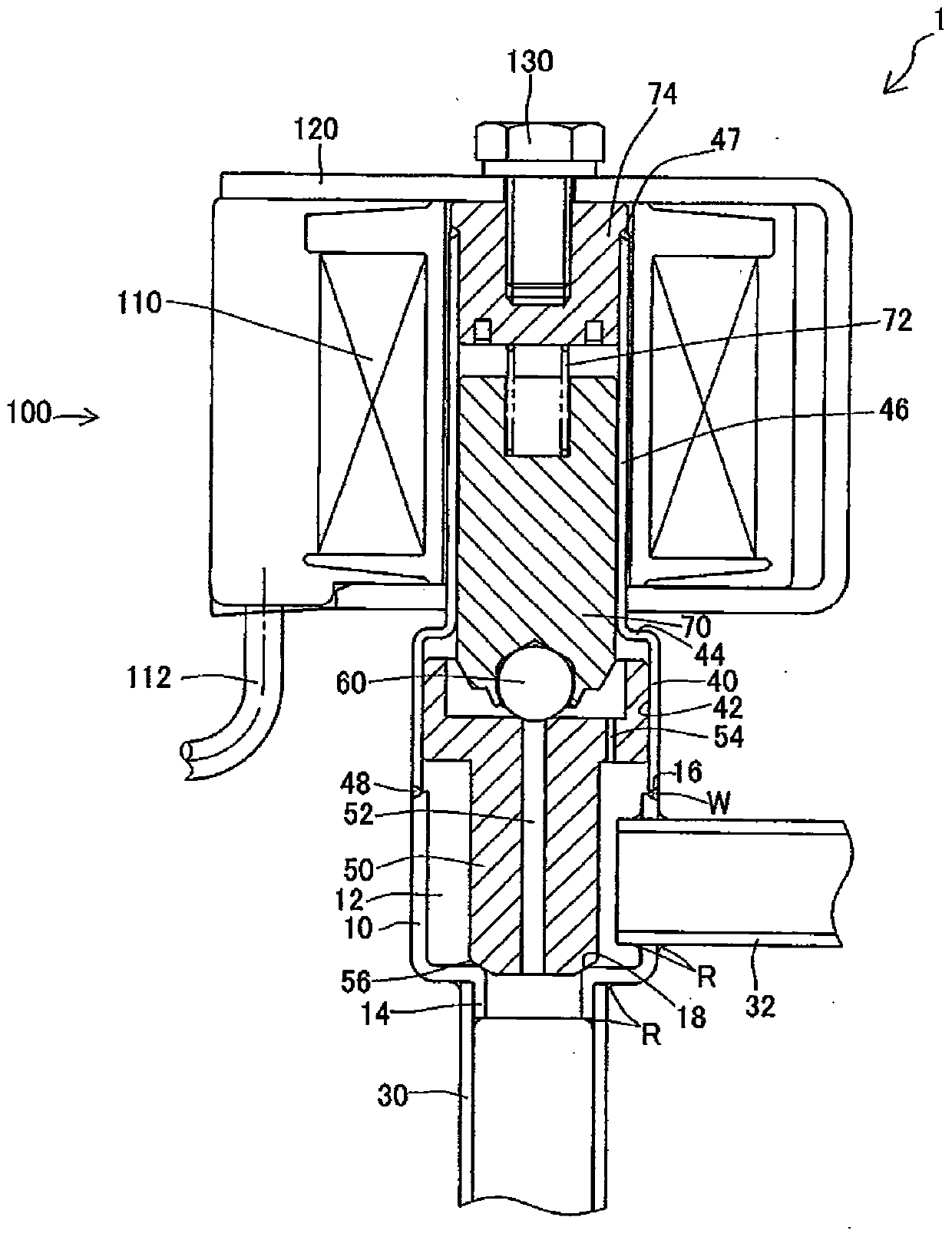
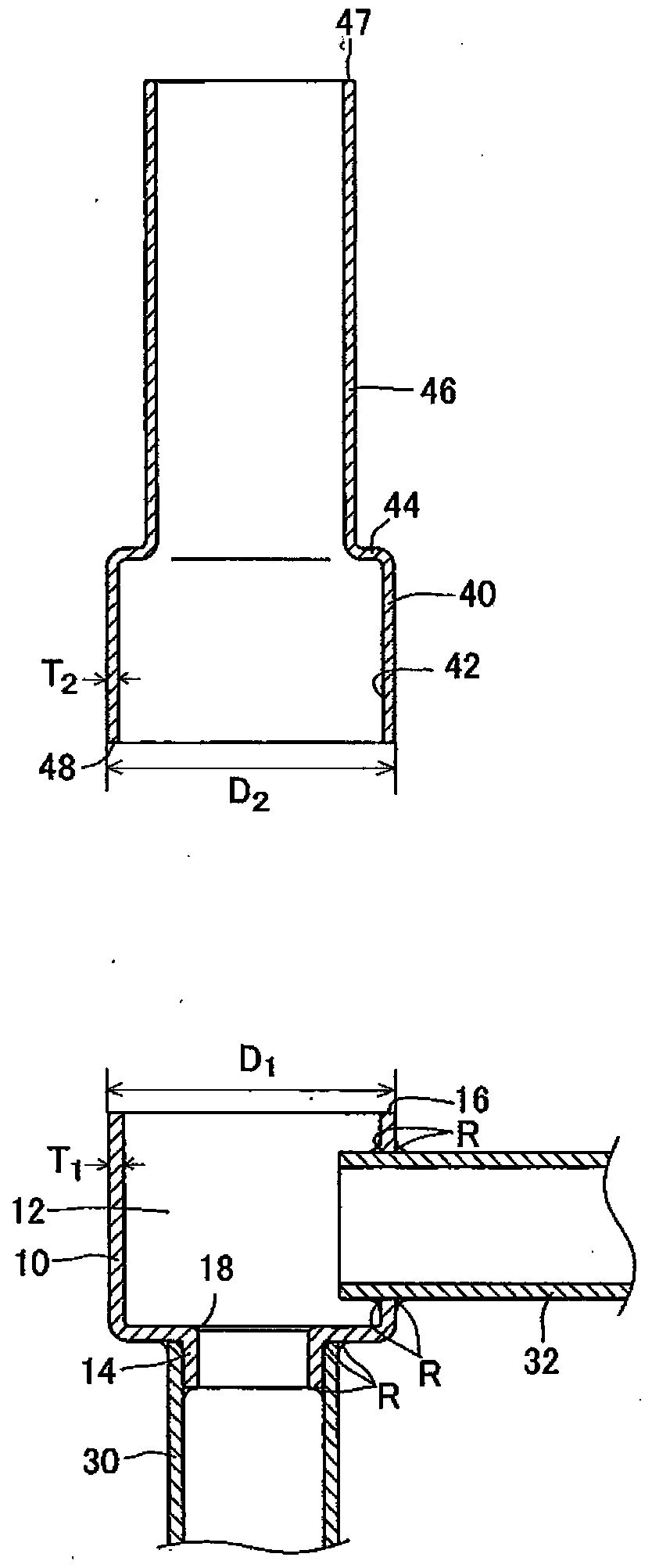
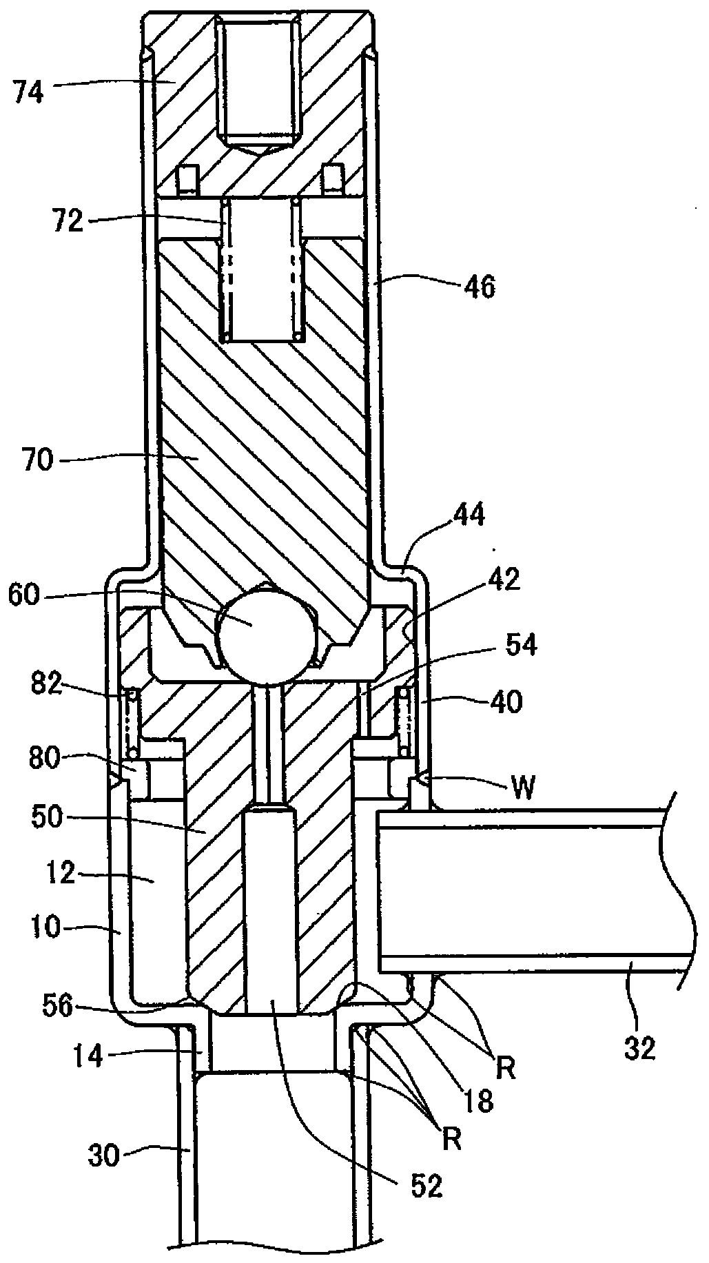
[0066] refer to figure 1 as well as figure 2 The solenoid valve 1 according to the first embodiment of the present invention will be described. The solenoid valve 1 has a valve body formed by joining the second valve body 10 and the first valve body 40 .

[0067] The cylindrical second valve body 10 has a pipe connection portion 14 provided in the axial direction, and is joined to the first pipe 30 by brazing R. As shown in FIG. The second pipe 32 is joined to the side wall of the second valve main body 10 by brazing R, and communicates with the valve chamber 12 .

[0068] The joint end portion 48 of the first valve body 40 is joined to the upper end surface 16 of the second valve body 10 by welding W by fusion welding. A valve element 50 is slidably disposed on the sliding surface 42 of the first valve body 40 , and the tapered portion 56 of the valve element 50 is in contact with and separated from the valve seat 18 of the second valve body 10 .

[0069] The valve core 5...


PUM


Abstract

A valve body of a solenoid valve (1) is formed by jointing a second valve body (10) and a first valve body (4) through fusion welding. Pipes (30, 32) are jointed with the second valve body through brazing (R). A valve core (50) is guided to slide by an internal circumferencial surface (42) of the first valve body (40). The first valve body (40) is not influenced by thermal deformation of brazing (R), so that good sliding performance of built-in components is guaranteed. According to the electric driving valve, thermal deformation of the sliding surface is avoided when the pipes are jointed with the valve body through brazing.

Description

technical field [0001] The invention relates to electrically driven valves such as solenoid valves and electric valves. Background technique [0002] In the solenoid valve and the electric valve, a spool is accommodated inside a cylindrical valve body. Furthermore, the movable element that drives the spool has a structure in which a plunger and a rotor are arranged inside the valve body, and the spool is operated through the movable element by an electromagnetic drive unit such as a stator installed outside the valve body. [0003] prior art literature [0004] patent documents [0005] Patent Document 1: Japanese Patent Laid-Open No. 2004-263823 [0006] The problem to be solved by the invention [0007] Such an electrically driven valve has two or more piping members fixed to the valve main body. [0008] As a method of fixing pipe members, brazing is widely used because it is advantageous in terms of cost. Brazing, furnace brazing technology is used in large-scale i...

Claims


Application Information

Patent Timeline
Patent Type & Authority Patents(China)
IPC IPC(8): F16K27/02F16K27/10
CPCF16K27/029F16K27/102
Inventor 樋口浩次东家友也
Owner FUJIKOKI MFG CO LTD
Why Eureka
Try Eureka