Special heat pipe device for ship

A heat pipe device and ship technology, which is applied in the ship field, can solve problems such as inability to realize circulation, not easy to dissipate heat, and consume energy for condenser heat dissipation, so as to achieve the effects of reducing energy consumption, increasing transmission speed, and speeding up transmission speed

Active Publication Date: 2014-12-03
JIANGSU NANTONG SHENTONG MACHINERY
View PDF4 Cites 3 Cited by
  • Summary
  • Abstract
  • Description
  • Claims
  • Application Information

AI Technical Summary

Problems solved by technology

At present, the heat pipes on the market have no obvious effect on heat dissipation, and the efficiency is low for occasions with high heat transfer density, and the process of circulation ca

Method used


Image

  • Special heat pipe device for ship
  • Special heat pipe device for ship
  • Special heat pipe device for ship

Examples


Embodiment 1

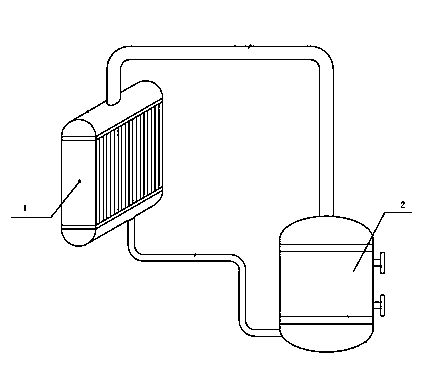
[0025] The present invention is based on the above structure, and the condenser 1 is arranged on the outside of the ship's chord, so that when the ship is running, the condenser can be washed by seawater to achieve cooling efficiency, and when the ship is stationary, the sea breeze can The blowing of the condenser can achieve the efficiency of cooling, and finally achieve the effect of reducing energy consumption; figure 1 As shown, the pipeline connecting the condenser 1 and the evaporator 2 includes an evaporation pipeline and a condensation pipeline, the condensation pipeline connects the lower surface of the condenser 1 and the evaporator 2, and the evaporation pipeline connects the upper surface of the condenser 1 and the evaporator 2; the heat pipe device Gravity heat pipe structure is adopted: the installation position of the condenser 1 is higher than that of the evaporator 2, so that it can rely on the height difference between the two and rely on the gravity of the me...

Embodiment 2

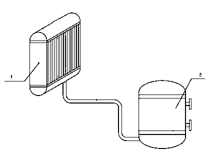
[0028] The present invention is on the basis of embodiment 1, as figure 2 As shown, a pipe connecting the condenser 1 and the evaporator 2 is also used. The use state of this device: when it transfers heat and dissipates heat, only one pipe is used to connect the condenser 1 and the evaporator 2, the evaporator 2 absorbs heat, flows the heat medium to the condenser 1, and dissipates the heat in the condenser 1 Transferred to the cold medium on the other side of the condensing end, the heat medium condenses into a liquid after releasing heat, and finally flows back to the evaporator 2 through the original pipeline.


PUM

PropertyMeasurementUnit
Wire diameteraaaaaaaaaa
Thicknessaaaaaaaaaa

Abstract

The invention discloses a special heat pipe device for a ship. The special heat pipe device comprises a condenser, an evaporator and a pipeline, wherein the condenser and the evaporator are communicated through the pipeline and form a loop, and the condenser is arranged on the outer side of a ship board. According to the special heat pipe device, the condenser is arranged on the outer side of the ship board, so that the cooling effect can be achieved through sea water scour of the condenser in a ship traveling process, the cooling effect can be achieved through sea breeze sway on the condenser in a stationary state of the ship, and finally, the energy consumption is reduced; the mounting position of the condenser is higher than that of the evaporator, so that self-circulation can be achieved by aid of the height difference between the condenser and the evaporator and the gravity action of a medium; and a stop valve arranged on the device can disconnect the loop timely when the anomaly occurs.

Description

technical field [0001] The invention relates to the technical field of ships, in particular to a special heat pipe device for ships. Background technique [0002] Heat pipe technology was widely used in aerospace, military and other industries before. Since it was introduced into the radiator manufacturing industry, people have changed the traditional radiator design ideas and got rid of the single heat dissipation mode that only relies on high air volume motors to obtain better heat dissipation. The use of heat pipe technology enables the radiator to achieve satisfactory results even if the radiator uses a low-speed, low-air-volume motor, which solves the noise problem that plagues air-cooled heat dissipation, and opens up a new world for the heat dissipation industry. The heat pipes currently on the market have little effect on heat dissipation, and are inefficient for occasions with high heat transfer density, and cannot realize the process of circulation. Generally, the...

Claims


Application Information

Patent Timeline
IPC IPC(8): F28D15/04
CPCF28D15/0266
Inventor 高峰顾忠华杜度郭峰
Owner JIANGSU NANTONG SHENTONG MACHINERY
Why Eureka
Try Eureka