Function module heat dissipation structure and case

A technology of functional modules and heat dissipation structure, which is applied in the construction of electrical equipment components, cooling/ventilation/heating transformation, electrical components, etc., can solve problems affecting equipment, circuits, shielding covers, slow heat dissipation, short circuit, burning, etc., to achieve simplification Installation steps, simple and optimized layout, and the effect of improving heat dissipation efficiency

Pending Publication Date: 2018-03-27
成都芯通软件有限公司
View PDF0 Cites 3 Cited by
  • Summary
  • Abstract
  • Description
  • Claims
  • Application Information

AI Technical Summary

Problems solved by technology

[0005] The purpose of the present invention is to provide a heat dissipation structure for functional modules in view of the problems of slow heat dissipation and low heat dissipation efficiency of the shielding cover in the prior art circuit system, which will affect the normal operation of equipment and circuits after heat concentration, and even short circuit and burnout And the chassis, the heat dissipation structure of this functional module changes the existing circuit system structure, so that the circuit system and the chassis can carry out effective heat transfer, so as to improve the heat dissipation efficiency and accelerate the heat dissipation. The heat dissipation structure is stable and reliable, and can ensure rapid heat dissipation , continuously distributed, and then protect the normal operation of the circuit system, so that each functional module, PCB circuit board and circuit system can work continuously, efficiently and reliably, and play good functional characteristics

Method used


Image

  • Function module heat dissipation structure and case

Examples


Embodiment 1

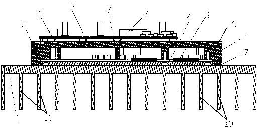
[0040] Functional module cooling structure, such as figure 1As shown, it includes a power amplifier substrate 2 for installation on the chassis 1, the power amplifier substrate 2 is connected with a first PCB board 4 with a power amplifier module 3, the first PCB board 4 is covered with a power amplifier shell 5, The outer edge of the power amplifier housing 5 is provided with a protruding portion 6, the protruding portion 6 extends along the surface direction of the first PCB board 4, and the extending direction is away from the center of the housing, and the protruding portion 6 extends to the chassis 1 at the same time The inner wall is in contact with the inner wall of the chassis 1.

[0041] As one of the implementations, the protruding portion 6 is continuously arranged along the outer edge of the power amplifier housing 5, forming a complete ring structure, and the protruding portion 6 and the power amplifier housing 5 are in an integrated structure. The part 6 is arra...

Embodiment 2

[0049] The heat dissipation case of the functional module is installed in the case with a power amplifier module 3 , and the power amplifier case 5 as described in the first embodiment is arranged on the power amplifier module 3 .

[0050] As one of the implementations, a plurality of power amplifier modules are arranged in the chassis 1, each of the power amplifier modules is correspondingly provided with the power amplifier housing, and each power amplifier module is correspondingly provided with a power amplifier housing, so as to improve the cooling efficiency.

[0051] As one of the implementation methods, such as figure 1 As shown, the outer wall of the chassis 1 is connected with heat dissipation teeth 10, and the heat dissipation teeth 10 are connected on the outer wall corresponding to the contact position between the raised portion 6 and the inner wall of the chassis 1. The heat dissipation teeth 10 can further improve the heat dissipation efficiency, and simultaneou...


PUM

PropertyMeasurementUnit
Thicknessaaaaaaaaaa

Abstract

The invention relates to the technical field of communication network equipment and in particular relates to a function module heat dissipation structure and a case. The function module heat dissipation structure disclosed by the invention comprises a power amplifier base board used for being mounted on the case, wherein a PCB (Printed Circuit Board) with a power amplifier module is connected ontothe power amplifier base board; a power amplifier shell covers the PCB; a protruding part is arranged on the outer edge of the power amplifier shell and extends along a board surface direction of thePCB, and the extension direction of the protruding part is far away from the center of the shell; and the protruding part simultaneously extends to inner walls of the case and is contacted with the inner walls of the case. According to the function module heat dissipation structure, the structural form of the existing circuit system is changed, so that effective heat transfer is performed betweenthe circuit system and the case, and the aims of improving the heat dissipation efficiency and accelerating heat dissipation are achieved. The heat dissipation structure is stable and reliable, the heat can be rapidly and continuously dissipated, and normal operation of the circuit system is further protected, so that each function module, the PCB and the circuit system can continuously, efficiently and reliably work, and excellent functional characteristics are achieved.

Description

technical field [0001] The invention relates to the technical field of communication network equipment, in particular to a heat dissipation structure of a functional module and a chassis. Background technique [0002] In the communication network equipment, multiple functional modules are arranged on the PCB circuit board, and each functional module correspondingly realizes different functions. Meanwhile, the multiple functional modules constitute the entire circuit system to realize the overall function of the circuit system. Each functional module emits a large amount of heat during operation, and how to quickly dissipate heat and keep the temperature of the circuit system within a controllable and normal range has become a key consideration in the layout of the circuit system. [0003] In the circuit system, there are mainly two heat dissipation methods for functional modules. One is to exchange heat with the air and dissipate heat through the air. It is in a non-circula...

Claims


Application Information

Patent Timeline
IPC IPC(8): H05K7/20
CPCH05K7/205
Inventor 冯亮肖相余余飞
Owner 成都芯通软件有限公司
Why Eureka
Try Eureka