Heat radiation device and lighting device

A technology of a heat dissipation device and a heat dissipation plate, applied in the field of lighting, can solve the problems of increasing the volume of the heat sink, unable to meet the requirements of the size of LED products, unable to effectively solve the problem of heat dissipation of high-power LEDs, etc., to achieve a good heat dissipation effect and solve the problem of heat dissipation. effect of the problem

Active Publication Date: 2010-01-20
SHENZHEN GLITTER GENERAL ELECTRIC CO LTD
View PDF8 Cites 0 Cited by
  • Summary
  • Abstract
  • Description
  • Claims
  • Application Information

AI Technical Summary

Problems solved by technology

However, since LEDs with higher power generate more heat, in order to achieve the required heat dissipation efficiency, the volume of the required heat sink also increases correspondingly, which also cannot meet the size requirements of LED products.
To sum up, the existing heat dissipation methods cannot effectively solve the heat dissipation problem of high-power LEDs

Method used


Image

  • Heat radiation device and lighting device
  • Heat radiation device and lighting device

Examples


Embodiment Construction

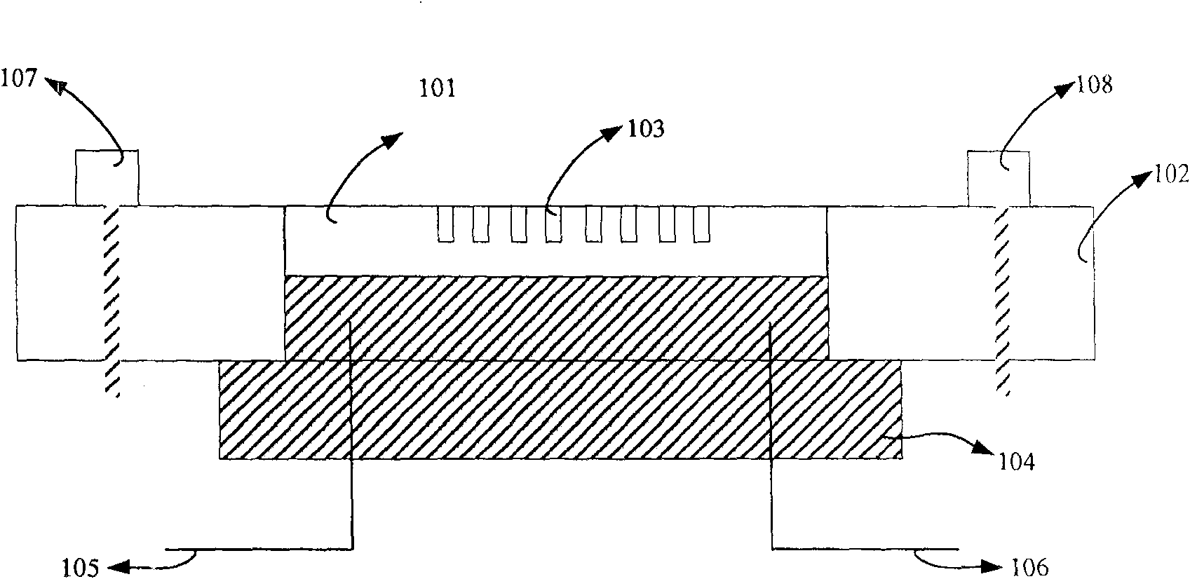
[0024] The invention provides a heat dissipation device, which uses a ceramic substrate with excellent characteristics such as high insulation, high heat conduction and high temperature resistance as a heat conduction plate to contact the heating body, and quickly conducts the heat generated by the heating body to the heat dissipation plate for heat dissipation .

[0025] Schematic diagram of the composition of the cooling device provided by the present invention, such as figure 1 As shown, the device includes: a ceramic substrate 101, a cooling plate 102;

[0026] Among them, in order to quickly transfer the heat generated by the heating element to the heat dissipation plate, the ceramic substrate is in contact with the surface of the heating element, and conducts the heat generated by the heating element to the heat dissipation plate; the heat dissipation plate and the ceramic substrate are bonded by thermally conductive adhesive.

[0027] In the embodiment of the present i...


PUM

PropertyMeasurementUnit
luminous efficiencyaaaaaaaaaa

Abstract

The disclosed heat sink comprises: a ceramic base to form the contact with heat radiator surface, and a heat distribution board adhered with the said base. Besides, the invention also discloses a luminescent device, which comprises: a conductive circuit connected with a plurality of semi-conductor luminescent devices, a ceramic base to transfer heat by conduction with these luminescent devices, a heat distribution board, a positive / negative lead wire connected with the conductive circuit, and a reflection cover arranged on former luminescent devices. This invention adds no size to luminescent device, and comes up to the heat dispersion efficiency.

Description

technical field [0001] The invention relates to the lighting field, in particular to a heat dissipation device used in the lighting field and a light emitting device using the heat dissipation device. Background technique [0002] The history of human lighting has gone through a long process of development. With the breakthrough of the third-generation wide-bandgap semiconductor material GaN (gallium nitride), semiconductor technology is gestating a new industrial revolution after the microelectronics revolution—the lighting revolution, whose symbol is based on semiconductor light-emitting diodes (LEDs). ) solid-state lighting (also known as "semiconductor lamp") will gradually replace incandescent and fluorescent lamps and enter the field of general lighting. [0003] LED solid-state lighting is considered to be a new energy-saving light source for lighting, because under the same brightness, the power consumption of semiconductor lamps is only 1 / 10 of that of ordinary inc...

Claims


Application Information

Patent Timeline
Patent Type & Authority Patents(China)
IPC IPC(8): H05K7/20H01L23/367F21V29/02F21V29/70F21V29/89
CPCH01L2924/0002
Inventor 陈荣华
Owner SHENZHEN GLITTER GENERAL ELECTRIC CO LTD
Why Eureka
Try Eureka