Method and device for measuring polarization characteristics of basic unit structure parameters of polarization-maintaining optical waveguide ring resonator

A ring resonant cavity and structural parameter technology, applied in the direction of testing optical performance, etc., can solve the problems of not considering the difference between the primary and secondary polarization states, not considering the resonant cavity, etc.

Inactive Publication Date: 2016-08-24
ZHEJIANG UNIV
View PDF7 Cites 0 Cited by
  • Summary
  • Abstract
  • Description
  • Claims
  • Application Information

AI Technical Summary

Problems solved by technology

However, in some previous test methods and devices that used the resonance curve of the ring resonator to obtain the coupling coefficient of the three basic unit structural parameters of the resonator (coupler coupling coefficient, coupler additional loss, and optical waveguide transmission loss), they did not consider The difference between the primary and secondary polarization states, that is, the existence of two primary and secondary polarization states in the resonator is not considered

Method used


Image

  • Method and device for measuring polarization characteristics of basic unit structure parameters of polarization-maintaining optical waveguide ring resonator
  • Method and device for measuring polarization characteristics of basic unit structure parameters of polarization-maintaining optical waveguide ring resonator
  • Method and device for measuring polarization characteristics of basic unit structure parameters of polarization-maintaining optical waveguide ring resonator

Examples


Embodiment Construction

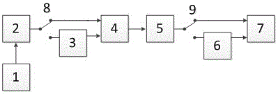
[0029] Such as figure 1 As shown, the optical waveguide ring resonator resonance curve and second harmonic demodulation curve test device includes a sawtooth wave signal generator 1, a laser 2, a phase modulator 3, an optical waveguide ring resonator 4, a PD detector 5, and a signal processing Circuit 6, oscilloscope 7, first single pole double throw switch 8, second single pole double throw switch 9; sawtooth wave signal generator 1, laser 2, one end of first single pole double throw switch 8, optical waveguide ring resonator 4, PD detection One end of the second single-pole double-throw switch 9 and the oscilloscope 7 are connected in sequence; or, the sawtooth wave signal generator 1, the laser 2, the other end of the first single-pole double-throw switch 8, the phase modulator 3, and the optical waveguide ring cavity 4. The PD detector 5, the other end of the second single-pole double-throw switch 9, the signal processing circuit 6, and the oscilloscope 7 are connected in s...


PUM


Abstract

The invention discloses a polarization characteristic testing method and device for basic unit structure parameters of a polarization-maintaining optical-waveguide annular resonant cavity. In the device, a sawtooth wave signal generator, a laser device, an end of a first single-pole double-throw switch, the optical-waveguide annular resonant cavity, a PD detector, an end of a second single-pole double-throw switch, and an oscilloscope are sequentially connected, or the sawtooth wave signal generator, the laser device, the other end of the first single-pole double-throw switch, a phase modulator, the optical-waveguide annular resonant cavity, the PD detector, the other end of the second single-pole double-throw switch, a signal processing circuit and the oscilloscope are sequentially connected. The invention provides an effective testing method for simply and directly obtaining a numerical relationship of three basic unit structure parameters of the optical-waveguide annular resonant cavity in primary and secondary polarization states without any destruction. Implementation of the method and device can provide guidance in further carrying out optimization design of a high-performance polarization-maintaining optical-waveguide resonant cavity so that the device and method are significantly important to improvement of limiting sensibility of a resonant-type miniature optical gyroscope and improvement of performance.

Description

Technical field [0001] The invention relates to a method and a device for testing the polarization characteristics of the basic unit structural parameters of a polarization-maintaining optical waveguide ring resonant cavity. Background technique [0002] The optical waveguide ring resonator is the core sensitive component of the resonant miniature optical gyroscope. Connecting one of the output ports and one of the input ports of a directional coupler constitutes the most basic structure of the ring resonator. In the resonant micro-optical gyroscope, in addition to the loss characteristics of the resonant cavity affecting the gyro performance, the polarization characteristics of the optical waveguide resonator also greatly affect the polarization fluctuation noise in the resonant micro-optical gyroscope. In order to improve the polarization characteristics of the optical waveguide resonator, in general high-precision gyroscope applications, polarization-maintaining optical wavegu...

Claims


Application Information

Patent Timeline
Patent Type & Authority Patents(China)
IPC IPC(8): G01M11/02
Inventor 马慧莲李学辉金仲和
Owner ZHEJIANG UNIV
Why Eureka
Try Eureka