
A dynamic simulation method for continuous leakage and diffusion of heavy gas

A dynamic simulation, leakage and diffusion technology, applied in special data processing applications, instruments, electrical digital data processing, etc., can solve the problems that the simulation structure is not accurate and intuitive, and the continuous leakage and diffusion process of heavy gas cannot be simulated dynamically.

Active Publication Date: 2017-06-16
SHANGHAI ADVANCED RES INST CHINESE ACADEMY OF SCI
View PDF2 Cites 0 Cited by
  • Summary
  • Abstract
  • Description
  • Claims
  • Application Information

AI Technical Summary

Problems solved by technology

[0009] In view of the above-mentioned shortcomings of the prior art, the purpose of the present invention is to provide a dynamic simulation method for the continuous leakage and diffusion of heavy gas, which is used to solve the problem that the continuous leakage of heavy gas that changes with time cannot be dynamically simulated by the flat plate model in the prior art. Diffusion process and simulation structure are not accurate and intuitive enough

Method used


Image

  • A dynamic simulation method for continuous leakage and diffusion of heavy gas
  • A dynamic simulation method for continuous leakage and diffusion of heavy gas
  • A dynamic simulation method for continuous leakage and diffusion of heavy gas

Examples


Embodiment 1

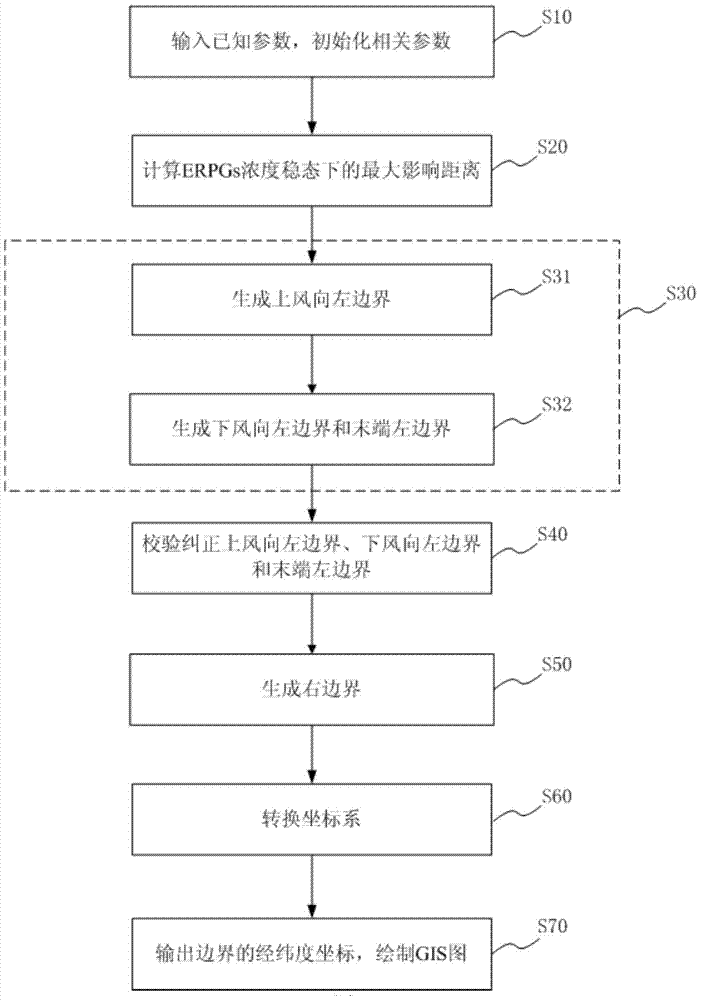
[0067] A dynamic simulation method for the continuous leakage and diffusion of heavy gas in this embodiment, specifically as figure 1 shown, including:

[0068] Step S10, input known parameters, and initialize related parameters according to known parameters:

[0069] Since this embodiment carries out the dynamic simulation of heavy gas continuous leakage and diffusion, its known parameters specifically include: wind speed u at a height of 10 meters, wind direction (angle), air pressure, air temperature, leakage source longitude long, leakage source latitude lat, leakage Source height h, initial density of heavy gas cloud, initial half-width of heavy gas cloud b 0 , the time t after the incident, the molecular weight of the leaked substance, the concentration c of ERPGs of the leaked substance, and the initial concentration c of the gas cloud 0 wait.

[0070] Initialization related parameters specifically include:

[0071] a. Convert the wind direction into radians: radian...

Embodiment 2

[0174] In order to illustrate the present invention more clearly, the initial parameters are set as:

[0175]

[0176]

[0177] Under the condition that the initial parameters are as described in the above table, the contour GIS effect map of ERPGs obtained by directly applying the plate model is as follows Figure 5 shown. Using the method of the present embodiment, the contour effect of the ERPGs solved is as follows:

[0178] 1) After 5 minutes of leakage from the leakage source, the GIS rendering of the contour line of ERPGs is as follows: Image 6 shown;

[0179] 2) 10 minutes after the leakage source, the GIS effect map of the contour line of ERPGs is as follows: Figure 7 shown;

[0180] 3) After 20 minutes of leakage from the leakage source, the GIS effect map of the contour line of ERPGs is as follows: Figure 8 shown;

[0181] 4) 30 minutes after the leakage source, the GIS effect map of the contour line of ERPGs is as follows: Figure 9 shown.

[0182]...


PUM


Abstract

The invention provides a method for dynamic simulation of continuous heavy gas drain diffusion. The method based on a slab model includes: inputting known parameters, and initializing relevant parameters according to the known parameters; calculating a maximum influence distance under an ERPGs (emergency response planning guidelines) concentration steady state; generating left borders under a local coordinate system, wherein the left borders include an upwind left border, a downwind left border and a tail-end left border; verifying and correcting boundary points of the left borders; generating right borders according to the calculated boundary points of the left borders; transforming coordinates of the border points of the left borders and the right borders into geographic coordinates; drawing a dynamic simulation GIS design sketch of continuous heavy gas drain diffusion according to the geographic coordinates. By adoption of the method, continuous heavy gas drain diffusion situation under the steady state can be simulated while a time-dependent process of continuous heavy gas drain diffusion can be dynamically simulated.

Description

technical field [0001] The invention relates to an emergency treatment technology for sudden accidents, in particular to a dynamic simulation method for continuous leakage and diffusion of heavy gas. Background technique [0002] Hazardous chemical leakage accidents are generally sudden, with a wide range of influence and serious consequences; especially heavy gas leakage accidents, such as chlorine gas, etc., because the density is higher than air, after the leakage, the heavy gas first sinks by gravity and then spreads along the ground, and then spreads along the ground. Coupled with the toxicity of the leaked substance itself, it will pose a great threat to the safety of people and the environment in the area affected by the leak, and may even cause a large number of casualties. Therefore, the control of leakage accidents has been paid more and more attention by the society. Researchers at home and abroad have carried out a series of studies on the continuous leakage and ...

Claims


Application Information

Patent Timeline
Patent Type & Authority Patents(China)
IPC IPC(8): G06F17/50
Inventor 刘道明魏建明徐俊张浩田欣
Owner SHANGHAI ADVANCED RES INST CHINESE ACADEMY OF SCI
Learn More