Voltage-controlled oscillator circuit

A voltage-controlled oscillator and circuit technology, applied in the direction of power oscillators, electrical components, etc., can solve the problems of large output noise of voltage-controlled oscillators, large oscillator variation range, large output noise and jitter, etc., to reduce output noise and jitter, improving performance and reducing gain requirements

Inactive Publication Date: 2014-12-03
长沙瑞达星微电子有限公司
View PDF6 Cites 5 Cited by
  • Summary
  • Abstract
  • Description
  • Claims
  • Application Information

AI Technical Summary

Problems solved by technology

[0004] In this existing voltage-controlled oscillator, when the voltage-controlled voltage is 0 and the bias current flowing through the PMOS transistor P1 is 0, the oscillation frequency is also 0.
This makes the frequency of the oscillator vary with the voltage-controlled voltage in a relatively large range, resulting in a relatively large tuning curve gain Kvco of the voltage-controlled oscillator
In general, there will be a certain amount of ripple on the voltage-controlled voltage, so a large tuning curve gain Kvco will cause relatively large output noise and jitter of the voltage-controlled oscillator, which will adversely affect its performance.
Moreover, since the existing voltage-controlled oscillator is composed of three-stage current-controlled inverting modules, the output voltage range of each stage is the entire power supply voltage range of the full swing, which leads to relatively large output noise of the voltage-controlled oscillator

Method used


Image

  • Voltage-controlled oscillator circuit
  • Voltage-controlled oscillator circuit
  • Voltage-controlled oscillator circuit

Examples


Embodiment Construction

[0017] The following will clearly and completely describe the technical solutions in the embodiments of the present invention with reference to the accompanying drawings in the embodiments of the present invention. Obviously, the described embodiments are only some, not all, embodiments of the present invention. Based on the embodiments of the present invention, all other embodiments obtained by persons of ordinary skill in the art without making creative efforts belong to the protection scope of the present invention.

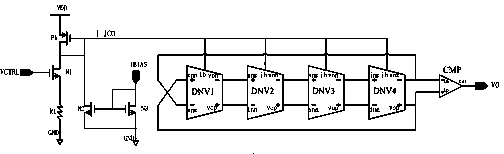
[0018] A voltage controlled oscillator circuit such as figure 2 As shown, it includes a voltage-controlled current generating circuit composed of MOS transistors N1, N2, N3, P1 and resistor R1 and a current-controlled oscillator module composed of differential inverting modules DNV1, DNV2, DNV3, DNV4 and comparator CMP; , the gate of the NMOS transistor N1 is connected to the input voltage VCTRL, the source is connected to the ground through the resistor R1, ...


PUM


Abstract

The invention provides a voltage-controlled oscillator circuit, and belongs to the field of integrated circuits. The voltage-controlled oscillator circuit comprises a voltage-controlled current generation circuit formed by MOS transistors N1, N2, N3 and P1 and a resistor R1 and a current-controlled oscillator module formed by differential inverse modules DNV1, DNV2, DNV3 and DNV4 and a comparator CMP. According to the voltage-controlled oscillator circuit, when voltage-controlled voltage is zero, an oscillator can also have a constant oscillation frequency. Thus, the range in which the frequency of the oscillator changes along with the voltage-controlled voltage is greatly reduced, the tuning curve gain of the voltage-controlled oscillator is also reduced, and output noise and shaking of the voltage-controlled oscillator are greatly reduced. In addition, four levels of delay unit circuits are adopted in the voltage-controlled oscillator circuit; on each level of output, NMOS transistors connected through diodes are used for limiting output voltage, therefore, the gain requirement and the output voltage range of each level of circuit are greatly reduced, and output noise is reduced.

Description

technical field [0001] The invention belongs to the field of integrated circuits, in particular to a voltage-controlled oscillator circuit. Background technique [0002] With the rapid development of communication technology, the voltage-controlled oscillator has become one of the research hotspots in the field of integrated circuits. It can provide frequency synthesis signals for frequency synthesizers, and can also generate local oscillation signals for mixers. [0003] figure 1 It is a circuit diagram of an existing voltage-controlled oscillator. In the circuit, the gate of the NMOS transistor N1 is connected to the input voltage VCTRL, the source is connected to the ground through the resistor R1, and the drain is connected to the node I_ICO; both the gate and the drain of the PMOS transistor P1 are connected to the node I_ICO, and the source of the PMOS transistor P1 is connected to the node I_ICO. Power supply VDD; the bias current terminals ib of the current control...

Claims


Application Information

Patent Timeline
Patent Type & Authority Applications(China)
IPC IPC(8): H03B5/32
Inventor 林剑辉
Owner 长沙瑞达星微电子有限公司
Why Eureka
Try Eureka