Electrically driven two-wheeled vehicle

A two-wheeled vehicle, electric drive technology, applied in the direction of electric vehicles, motor vehicles, control drive, etc., to achieve the effect of high motor speed

Inactive Publication Date: 2014-12-03
ROBERT BOSCH GMBH
View PDF6 Cites 1 Cited by
  • Summary
  • Abstract
  • Description
  • Claims
  • Application Information

AI Technical Summary

Problems solved by technology

[0004] The disadvantage of this embodiment is that the electric machine can only be operated usably in the range of the armature adjustment

Method used


Image

  • Electrically driven two-wheeled vehicle
  • Electrically driven two-wheeled vehicle
  • Electrically driven two-wheeled vehicle

Examples


Embodiment Construction

[0026] figure 1 An electrically driven two-wheeled vehicle 1 is shown in a perspective view, the front wheels 2 of which can be steered and the rear wheels 3 of which can be driven by means of an electric motor 4 , which is here designed as a wheel motor 5 . The electric machine 4 has a shaft-mounted stator 6 and a rim-mounted rotor 7 , the rotor 7 being arranged coaxially with the stator 6 and aligned.

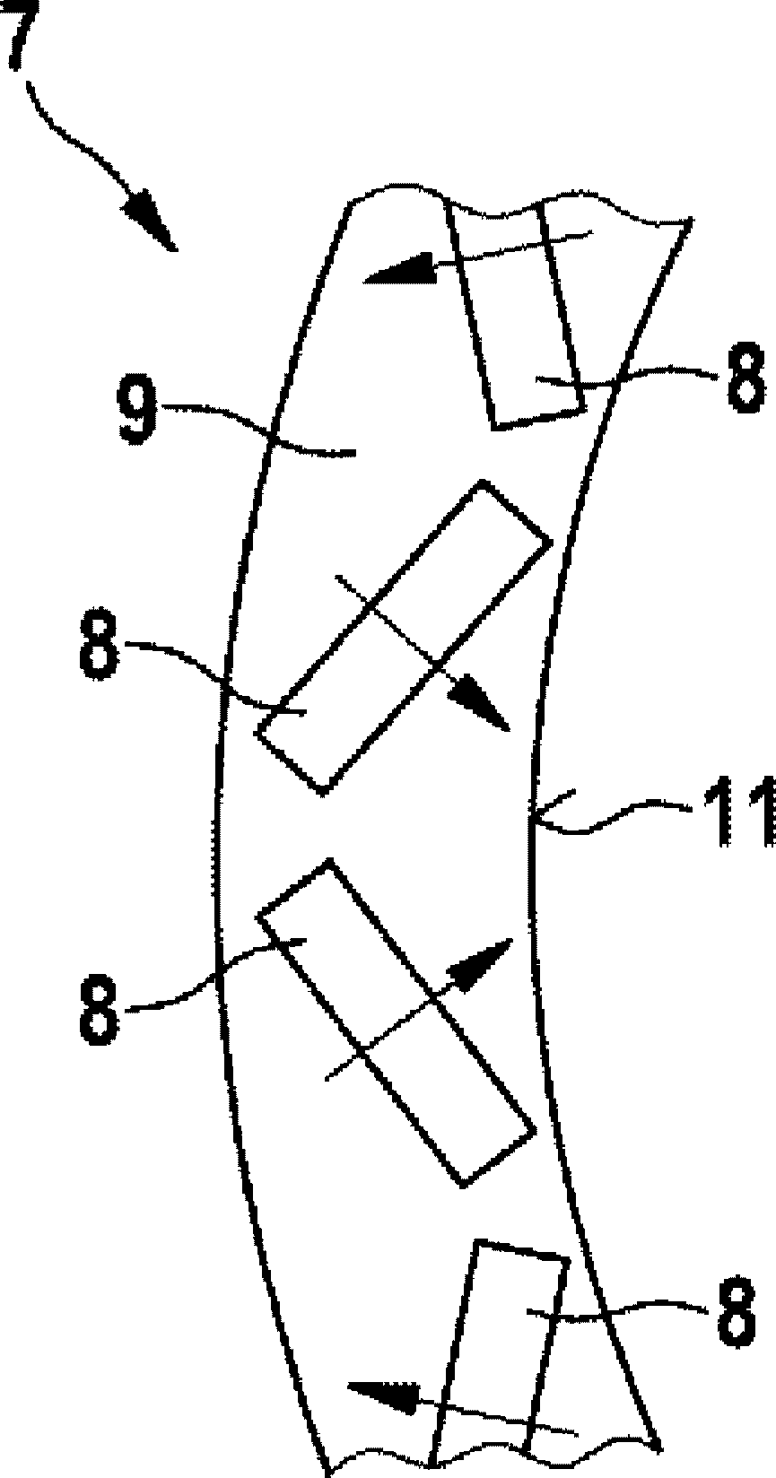
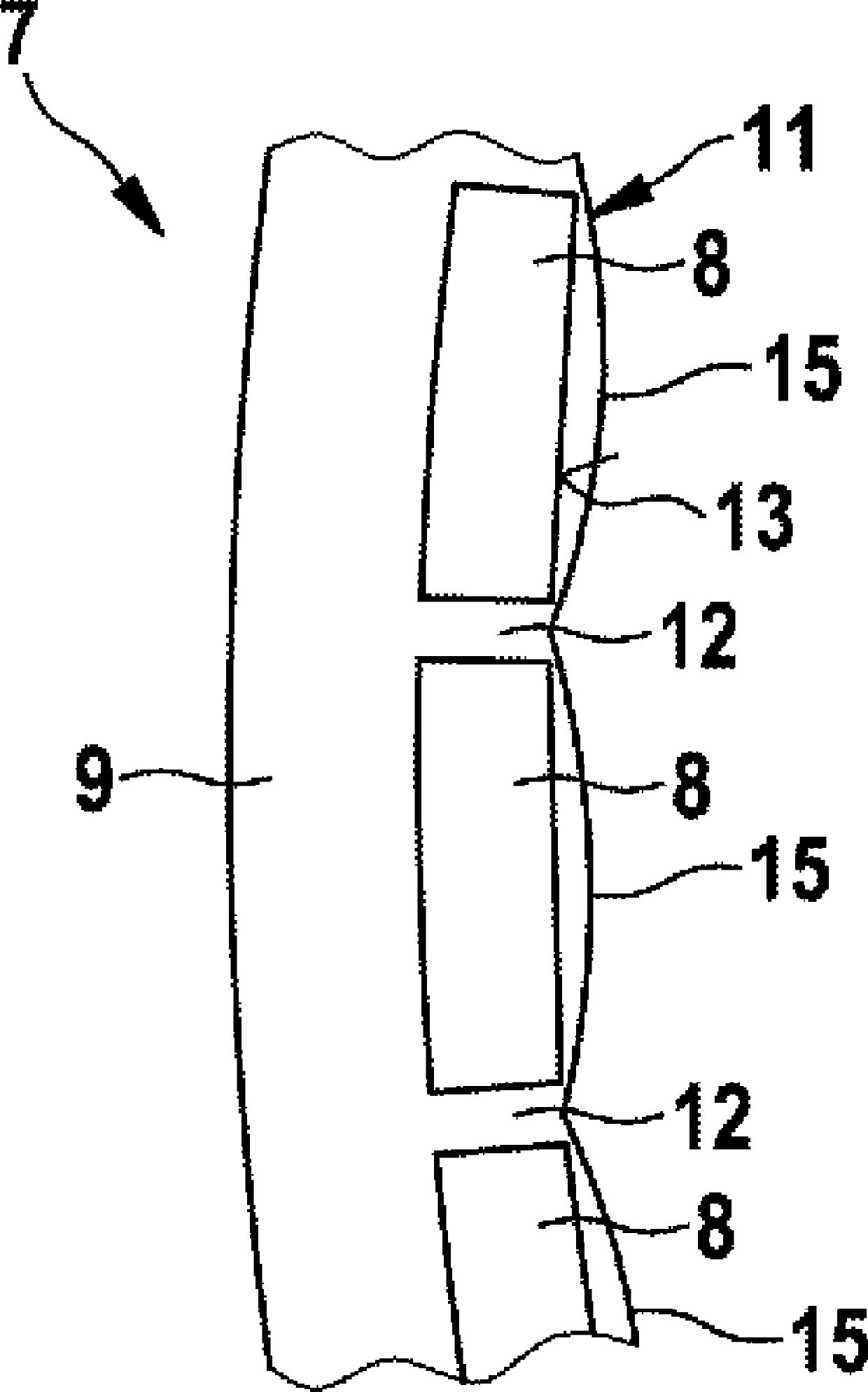
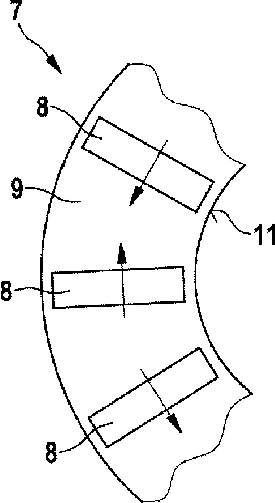
[0027] The rotor 7 is usually provided with a plurality of permanent magnets, typically rare earth magnets, arranged next to one another on the inside. Conventional constructions have the disadvantage that known rotors have hardly any significant saliency. The concept of saliency from the English "salience" should refer to the attached Figure 2A and 2B for a more detailed explanation. In the rotor-fixed coordinate system of a permanently excited synchronous machine, the so-called q-axis describes the direction of the magnetic flux of the ground ring 9 generated by the st...


PUM


Abstract

The invention relates to an electrically driven two-wheeled vehicle (1) comprising at least one electric machine (4) which has a stator (6) that is fixed to the axle and a rotor (7) that is fixed to the rim. The rotor (7) has a back iron ring (9) with a plurality of permanent magnets (8) which are distributed over the circumference of the back iron ring. The back iron ring (9) has pockets (10) on the back iron ring inner face (11) facing the stator (6), one permanent magnet (8), in particular a ferrite magnet, being at least substantially arranged in each said pocket. The invention further relates to a method for actuating such a two-wheeled vehicle.

Description

technical field [0001] The invention relates to an electrically driven two-wheeled vehicle having at least one electric motor with a shaft-fixed stator and a rim-fixed rotor, wherein the rotor has a grounding ring with a plurality of Permanent magnets on the perimeter. [0002] Furthermore, the invention relates to a method for operating such a two-wheeled vehicle. Background technique [0003] Two-wheeled vehicles of the type mentioned at the outset are known from the prior art. In particular, electric vehicles are frequently operated in the power class up to 4 kW, and in some cases also in the power class up to 11 kW, with driveless hub motors on the rear wheels. Such electric machines are generally brushless, electrically commutated electric machines. It has a shaft-fixed stator with often high usage. The rotor interacting with the stator is a direct component of the rim or is fixedly arranged and typically has a ring of permanent magnets, in particular rare-earth mag...

Claims


Application Information

Patent Timeline
IPC IPC(8): B62M6/65B62M6/40H02K21/22H02K1/27
CPCH02K7/14B60L2220/44B62M6/65B60L15/20B60L15/025B62M6/40B60L2220/18B60L2200/12H02K1/2786Y02T10/72Y02T10/64H02K1/2791
Inventor S.A.埃万斯A.施图布纳N.马丁M.迪特里希程凤妹
Owner ROBERT BOSCH GMBH
Why Eureka
Try Eureka