Coil
A coil and phase coil technology, applied in the shape/style/structure of the winding conductor, etc., can solve the problems of increased time, complicated coil winding process, and increased equipment cost.
- Summary
- Abstract
- Description
- Claims
- Application Information
AI Technical Summary
Problems solved by technology
Method used
Image
Examples
no. 1 approach
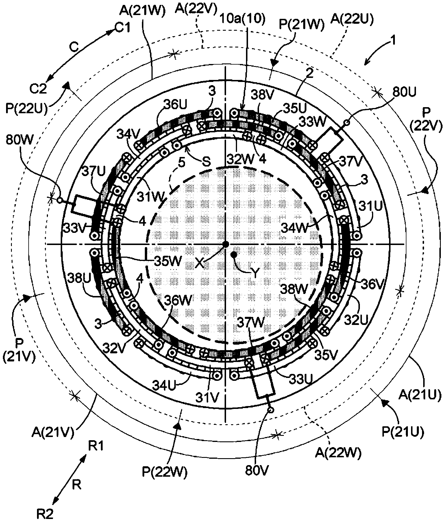
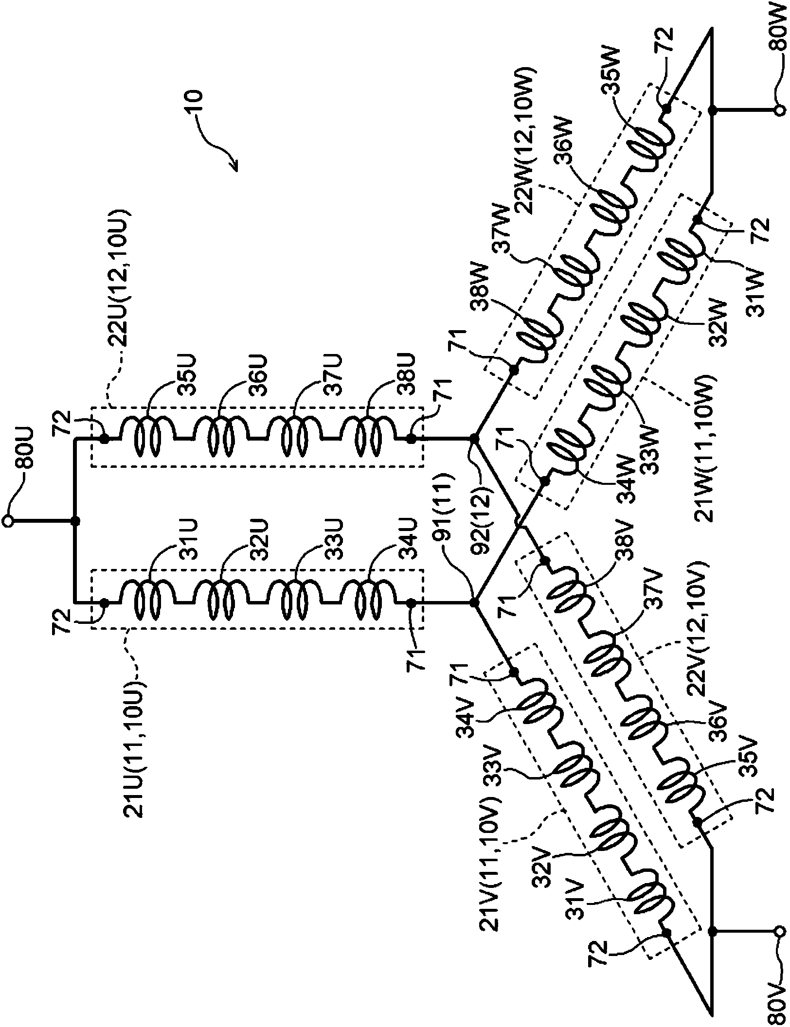
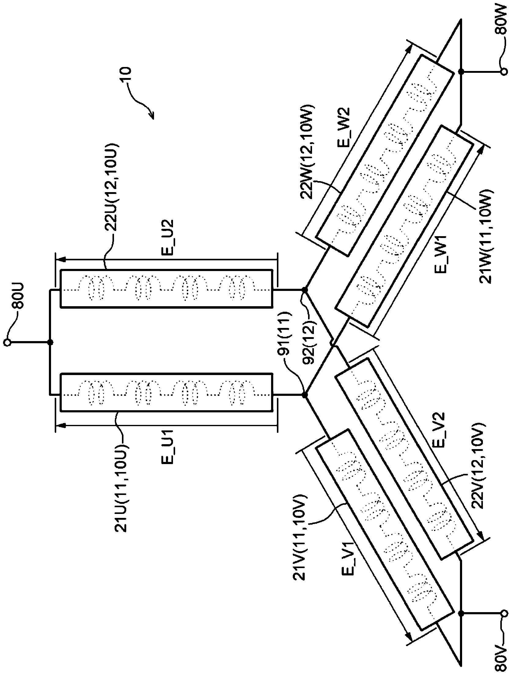
[0029] A first embodiment of the coil of the present invention will be described with reference to the drawings. Here, the coil of the present invention is applied to a coil for a rotating electrical machine, specifically, to a coil 10 wound around a stator core 2 of a stator 1 (see figure 1 ) case as an example. Such as figure 1 As shown, the stator 1 of this embodiment is a stator for an inner rotor type rotating electric machine. In this specification, a rotating electrical machine is used as any concept including a motor (electric motor), a generator (generator), and a motor generator that functions as both a motor and a generator as needed. In this embodiment, the stator core 2 corresponds to the "core" in the present invention.
[0030] In the following description, unless otherwise specified, "axial direction", "circumferential direction C", and "radial direction R" refer to the cylindrical iron core reference plane S (refer to figure 1 ) axis is defined as a dat...
no. 2 approach
[0069] refer to Figure 11 as well as Figure 12 A second embodiment of the coil of the present invention will be described. This embodiment differs from the first embodiment described above in that "N" is "4". Hereinafter, differences from the above-mentioned first embodiment will be mainly described, and points not particularly indicated are the same as those of the above-mentioned first embodiment.
[0070] Such as Figure 12 As shown, in this embodiment, the coil 10 has a first star connection body 11, a second star connection body 12, a third star connection body 13, and a fourth star connection body 14, a total of four star connections body. The four star connection bodies 11 to 14 are divided into three phase coil parts respectively corresponding to the three phases, and the first ends 71 of the three phase coil parts are independently formed by each star connection body 11 to 14 The neutral points 91-94 are connected. In addition, in the present embodiment, eac...
no. 3 approach
[0077] refer to Figure 13 A third embodiment of the coil of the present invention will be described. exist Figure 13 in, with figure 1 Similarly, only the folded-back portion of the unit coil portion is shown, and the illustration of the overlapping portion and connecting members between the coil end portion 10 a and the neutral points 91 and 92 is omitted. In this embodiment, the shapes of the U-phase unit coil parts 31U to 38U, the V-phase unit coil parts 31V to 38V, and the W-phase unit coil parts 31W to 38W (turned-back parts) when viewed along the axial direction L, and the The overall arrangement shape of the coil end portion 10a when viewed in the L direction is different from the shape of the first embodiment described above. In the above first embodiment, if figure 1 As shown, the shape of each unit coil portion (folded portion) viewed along the axial direction L is an arc shape along the circumferential direction C. Furthermore, in the first embodiment descr...
PUM
 Abstract
Description
Claims
Application Information
 - R&D
- Intellectual Property
- Life Sciences
- Materials
- Tech Scout
- Unparalleled Data Quality
- Higher Quality Content
- 60% Fewer Hallucinations
Browse by: Latest US Patents, China's latest patents, Technical Efficacy Thesaurus, Application Domain, Technology Topic, Popular Technical Reports.
© 2025 PatSnap. All rights reserved.Legal|Privacy policy|Modern Slavery Act Transparency Statement|Sitemap|About US| Contact US: help@patsnap.com


