Steel tube cold-drawing machine

A technology of cold drawing machine and steel pipe, which is applied in the field of steel pipe cold drawing machine, can solve problems such as low efficiency and affecting enterprise benefits, and achieve the effects of improving efficiency, saving time and improving production efficiency

Active Publication Date: 2014-12-10
ZHANGJIAGANG CITY SHENGDINGYUAN PIPE MAKING
View PDF8 Cites 6 Cited by
  • Summary
  • Abstract
  • Description
  • Claims
  • Application Information

AI Technical Summary

Problems solved by technology

[0003] Among them, the current general seamless steel pipe cold drawing equipment is to extend the blank steel pipe out of the outer die hole of the cold drawing machine, so that the cold drawing trolley can clamp the hammer head for cold drawing, but the existing cold drawing When the machine is cold-drawing, it can only cold-draw one steel pipe at a time. After cold-drawing a steel pipe, there will be a large amount of lubricating oil residue at the mold on the mold base, which needs to be cleaned before the next step of cold-drawing. pull out, its efficiency is very low, which seriously affects the benefit of the enterprise

Method used


Image

  • Steel tube cold-drawing machine

Examples


Embodiment 1

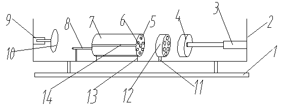
[0020] Such as figure 1 Described a kind of steel pipe cold drawing machine comprises base 1, frame 2, is provided with drawing die base 12 on described frame 2, and described drawing die base 12 becomes a disc-shaped structure, is arranged on it There are a plurality of mounting holes, a mold is arranged in the mounting holes, the die base 12 is installed on the frame 2 through the die support 11, and the die base support 11 is fixed on the on rack 2.

[0021] The two ends of the drawing die base 12 are respectively provided with a steel pipe positioning seat 7 and a drawing die clamp 4. The steel pipe positioning seat 7 is a cylindrical structure, and a plurality of steel pipe positioning holes 5 are arranged on it. The number of positioning holes 5 is the same as the number of mounting holes arranged on the drawing die base 12. In this embodiment, there are 6 steel pipe positioning holes 5, and the 6 steel pipe positioning holes are evenly distributed on the steel pip...

Embodiment 2

[0025] As an effective supplement to Embodiment 1 of the present invention, a positioning seat support bar 8 is provided on the frame 2, and the positioning seat support bar includes a vertical bar and a horizontal bar, and the vertical bar is connected to the described The frames are connected by welding or riveting, the center of the steel pipe positioning seat 7 is provided with a positioning seat support hole 6, and the horizontal bar is connected with the positioning seat support 6. When the steel pipe support seat 7 is installed, it is only necessary to put the positioning seat support hole 6 on the steel pipe support seat 7 on the horizontal bar, and rotate the steel pipe support seat 7 at the same time, only need to align the positioning clamp 13 with the limit slot Live on the line, just can complete the location of steel pipe support seat 7.

[0026] The steel pipe cold drawing machine of the present invention can draw multiple steel pipes at one time by setting mult...


PUM


Abstract

The invention discloses a steel tube cold-drawing machine which comprises a base and a rack, wherein a die stand is arranged on the rack and is provided with a plurality of installing holes; dies are arranged in the installing holes; the die stand is arranged on the rack; two ends of the die stand are respectively provided with a steel pipe positioning seat and a die drawing clamp. According to the steel tube cold-drawing machine, by arranging a plurality of dies on the die stand, a plurality of steel pipes can be drawn one time, so that the production efficiency is greatly improved; the plurality of steel pipes can be well supported by arranging the steel pipe positioning seat, and the steel pipes can be installed and positioned fast during production of the steel pipes, so that the time is saved, the efficiency is improved, the to-be-drawn steel pipes can be effectively supported, the stability in drawing and feeding is improved, and the production safety is improved.

Description

technical field [0001] The invention relates to a steel pipe production equipment, in particular to a steel pipe cold drawing machine. Background technique [0002] The production of seamless steel pipes needs to go through inspection, pickling, phosphating, saponification, cold drawing, heat treatment, and straightening from the beginning of the tube blank. [0003] Among them, the current general seamless steel pipe cold drawing equipment is to extend the blank steel pipe out of the outer die hole of the cold drawing machine, so that the cold drawing trolley can clamp the hammer head for cold drawing, but the existing cold drawing When the machine is cold-drawing, it can only cold-draw one steel pipe at a time. After cold-drawing a steel pipe, there will be a large amount of lubricating oil residue at the mold on the mold base, which needs to be cleaned before the next step of cold-drawing. Pulling out, its efficiency is very low, which seriously affects the benefit of th...

Claims


Application Information

Patent Timeline
Patent Type & Authority Applications(China)
IPC IPC(8): B21C1/22
Inventor 陈惠明
Owner ZHANGJIAGANG CITY SHENGDINGYUAN PIPE MAKING
Why Eureka
Try Eureka