Die structure for hot upset forging of stainless steel bolt

A technology of stainless steel and bolts, which is applied in the direction of bolts, connecting components, manufacturing tools, etc., can solve the problems of low production efficiency, high processing cost, explosive molds, etc., and achieve the effects of improving service life, saving mold costs, and convenient replacement

Inactive Publication Date: 2014-12-10
DONGGUAN SHING HING METAL MFG
View PDF7 Cites 10 Cited by
  • Summary
  • Abstract
  • Description
  • Claims
  • Application Information

AI Technical Summary

Problems solved by technology

[0002] Due to the particularity of the stainless steel material, when using the cold heading method to form a part with a relatively large head upsetting ratio (such as a stainless steel T-shaped bolt), the head is easily hardened by cold work due to severe deformation, resulting in the next step of cold deformation of the blank. Even if the billet is re-annealed and then cold-formed, it is easy to explode the mold, because annealing will definitely change the crystal structure of the material. If the annealing time is too long and too thorough, it will cause the crystal of the entire billet to refine and the billet will become soft, seriously affecting The mechanical properties of the rod portion (need to form the thread) with appropriate hardness and strength are required, resulting in a decrease in the performance of the product; and if the annealing time is used to ensure the strength of the billet rod portion, the cold work hardening of the head of the billet cannot be completely eliminated. , it is easy to cause frequent mold explosion during cold forming
[0003] Therefore, the stainless steel bolts with large upsetting ratio (such as stainless steel T-bol

Method used


Image

  • Die structure for hot upset forging of stainless steel bolt
  • Die structure for hot upset forging of stainless steel bolt
  • Die structure for hot upset forging of stainless steel bolt

Examples


Embodiment Construction

[0020] The present invention and its beneficial effects will be further described in detail below in conjunction with examples, but the embodiments of the present invention are not limited thereto.

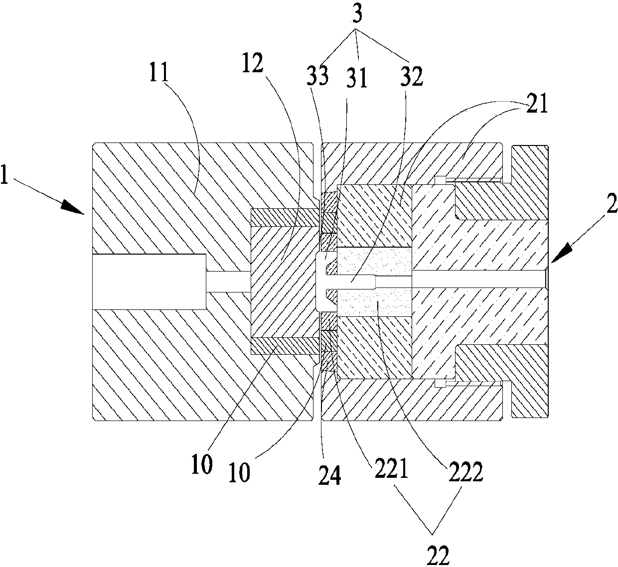
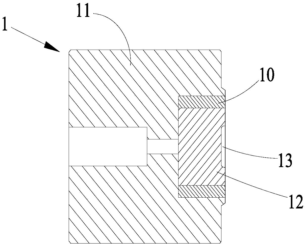
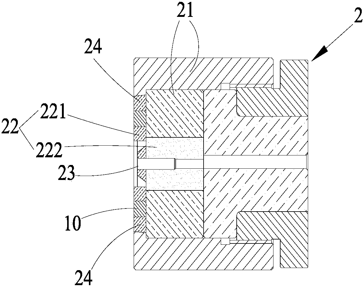
[0021] Such as Figures 1 to 3 As shown, the die structure for hot upset forging of a stainless steel bolt provided by the present invention includes a die 2 and a punch 1, and the punch 1 includes a first mold shell 11, a first mold core 12 and a first cavity 13, The first mold core 12 is placed in the first mold shell 11, and the first cavity 13 is arranged on the first mold core 12; the die 2 includes a second mold shell 21, a second mold core 22 and a second cavity 23, The second mold core 22 is placed in the second mold shell 21 , the second mold cavity 23 is disposed on the second mold core 22 , and the first mold cavity 13 and the second mold cavity 23 jointly form a space for accommodating the bolt 3 . In the present invention, the concave mold 2 and the convex mold 1 are...


PUM


Abstract

The invention belongs to the technical field of dies, and particularly relates to a die structure for hot upset forging of a stainless steel bolt. The die structure comprises a female die and a male die, wherein the male die comprises a first die shell, a first die core and a first cavity, the first die core is placed in the first die shell, the first cavity is formed in the first die core, the female die comprises a second die shell, a second die core and a second cavity, the second die core is placed in the second die shell, the second cavity is formed in the second die core, and a containing space for the bolt is jointly formed by the first cavity and the second cavity. According to the die structure, compared with the prior art, the female die and the male die are arranged to be of a split structure with parts replaceable, and thus replacement can be performed more conveniently and fast; if some part in a die is damaged, the die does not need to be scrapped as a whole, only the damaged part needs to be replaced, and therefore die cost is greatly reduced, and the service life of the whole die is prolonged.

Description

technical field [0001] The invention belongs to the technical field of dies, and in particular relates to a die structure for hot upset forging of stainless steel bolts. Background technique [0002] Due to the particularity of the stainless steel material, when using the cold heading method to form a part with a relatively large head upsetting ratio (such as a stainless steel T-shaped bolt), the head is easily hardened by cold work due to severe deformation, resulting in the next step of cold deformation of the blank. Even if the billet is re-annealed and then cold-formed, it is easy to explode the mold, because annealing will definitely change the crystal structure of the material. If the annealing time is too long and too thorough, it will cause the crystal of the entire billet to refine and the billet will become soft, seriously affecting The mechanical properties of the rod portion (need to form the thread) with appropriate hardness and strength are required, resulting ...

Claims


Application Information

Patent Timeline
IPC IPC(8): B21J13/02B21K1/50
Inventor 唐锦雄沈成汉彭波
Owner DONGGUAN SHING HING METAL MFG
Why Eureka
Try Eureka