
Manufacturing method of oil-way hole in base space and locating tool of oil-way hole

A technology for positioning tooling and oil passage holes, which is applied to positioning devices, manufacturing tools, metal processing equipment, etc., and can solve problems such as difficulty in guaranteeing processing quality, intersection and dislocation of deep oil passage holes on the side of the positioning reference, and small holes on the bottom surface, affecting quality, etc. , to achieve the effects of improving production efficiency, avoiding cumulative positioning errors, and improving accuracy

Inactive Publication Date: 2014-12-10
SHANGHAI RADIO EQUIP RES INST
View PDF3 Cites 0 Cited by
  • Summary
  • Abstract
  • Description
  • Claims
  • Application Information

AI Technical Summary

Problems solved by technology

[0002] The base of some servo mechanisms in the prior art is the key component of the servo mechanism. The base is generally a complex structure with multiple surfaces. The blank of the base is a forged aluminum cold-pressed part. The processing of these oil passage deep holes has always been a difficult problem in the processing and manufacturing of the base of the servo mechanism.
The current production method is to use ordinary milling machines to process each deep hole by repeatedly adjusting the position and angle of the base. The deep holes of the oil passage on the side of general milling are positioned by the shape, while the small oil passage holes on the bottom are drilled by the clamp machine. Die positioning processing, due to the inconsistency of the positioning datum, the intersection and dislocation of the deep hole of the side oil passage and the small hole on the bottom surface often occur during the processing, and the processing quality is difficult to guarantee, which has become a common problem affecting the quality

Method used


Image

  • Manufacturing method of oil-way hole in base space and locating tool of oil-way hole
  • Manufacturing method of oil-way hole in base space and locating tool of oil-way hole
  • Manufacturing method of oil-way hole in base space and locating tool of oil-way hole

Examples


Embodiment Construction

[0030] The present invention will be further elaborated below by describing a preferred specific embodiment in detail in conjunction with the accompanying drawings.

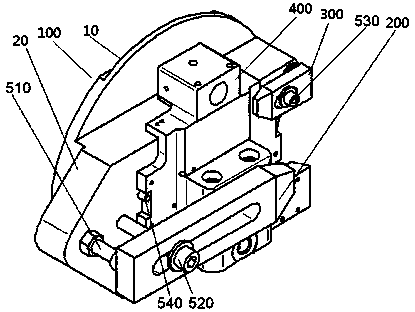
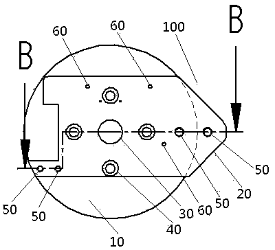
[0031] like Figure 1-Figure 3 As shown, a positioning tool for manufacturing oil passage holes in the base space, the tooling includes: a base 100; a pressure plate 200 arranged on the end surface of the workpiece 400 to be processed and connected to the base 100; arranged on the end surface of the workpiece 400 to be processed, and The compression fixing block 300 connected with the base 100 .

[0032] The base 100 includes: a circular chassis 10 ; The base 100 is provided with a tooling center hole 30 , and the tooling center hole 30 is set at the center of the chassis 10 and communicates with the mounting bracket 20 .

[0033] One end of the mounting bracket 20 is triangular, and the other end is "concave". The triangular end of the mounting bracket 20 extends outside the chassis 10 , and the “concave” end...


PUM


Abstract

The invention discloses a manufacturing method of an oil-way hole in a base space and a locating tool of the oil-way hole. The locating tool comprises a base, a pressure plate and a pressing fixed block, wherein the pressure plate is arranged at the end face of a to-be-processed part, and is connected with the base; the pressing fixed block is arranged at the end face of the to-be-processed part, and is connected with the base; the base comprises a round base plate, and a mounting bracket which is fixedly arranged in the middle of the end face of the base plate; one end of the mounting bracket is triangular; the other end of the mounting bracket is concave; the triangular end of the mounting bracket extends to the outside of the base plate; the concave end of the mounting bracket is arranged on the base plate. According to the invention, the base of a servo mechanism and the locating tool are arranged on a numerical control dividing head system based on the design of the locating tooling, and processing of a common machine tool is replaced with a numerical control integrated technology. The processing and manufacturing of the oil-way hole in the base space can be quickly and effectively carried out by the manufacturing method disclosed by the invention.

Description

technical field [0001] The invention relates to the technical field of processing deep holes and space intersecting holes, in particular to a method for manufacturing an oil passage hole in a base space and a positioning tool thereof. Background technique [0002] The base of some servo mechanisms in the prior art is the key component of the servo mechanism. The base is generally a complex structure with multiple surfaces. The blank of the base is a forged aluminum cold-pressed part. The processing of these oil passage deep holes has always been a difficult problem in the processing and manufacturing of the base of the servo mechanism. The current production method is to use ordinary milling machines to process each deep hole by repeatedly adjusting the position and angle of the base. The deep holes of the oil passage on the side of general milling are positioned by the shape, while the small oil passage holes on the bottom are drilled by the clamp machine. Die positioning ...

Claims


Application Information

Patent Timeline
Patent Type & Authority Applications(China)
IPC IPC(8): B23C3/00B23Q3/06
Inventor 梁石陈路韩斌
Owner SHANGHAI RADIO EQUIP RES INST
Learn More