Clamping and positioning device for machining gas turbine power turbine guide vane datum face

A technology for gas turbines and power turbines, applied in positioning devices, clamping devices, metal processing machinery parts, etc., can solve problems such as damage to steam channels, steam channels and steam channel circular arc assembly positioning, etc., to improve efficiency and process Stable, compact and reliable results

Active Publication Date: 2014-12-10
HARBIN TURBINE +1
View PDF7 Cites 15 Cited by
  • Summary
  • Abstract
  • Description
  • Claims
  • Application Information

AI Technical Summary

Problems solved by technology

[0003] The present invention aims to solve the problem that there is no special fixture device in the process of processing the guide vane of the power turbine of the existing gas turbine, the assembly and positioning of the steam channel and the circular arc of the steam channel are inconsistent, and the problem that the steam channel is damaged, and further provides a method for processing the guide vane of the gas turbine power turbine. Clamping device for blade datum plane

Method used


Image

  • Clamping and positioning device for machining gas turbine power turbine guide vane datum face
  • Clamping and positioning device for machining gas turbine power turbine guide vane datum face
  • Clamping and positioning device for machining gas turbine power turbine guide vane datum face

Examples


specific Embodiment approach 1

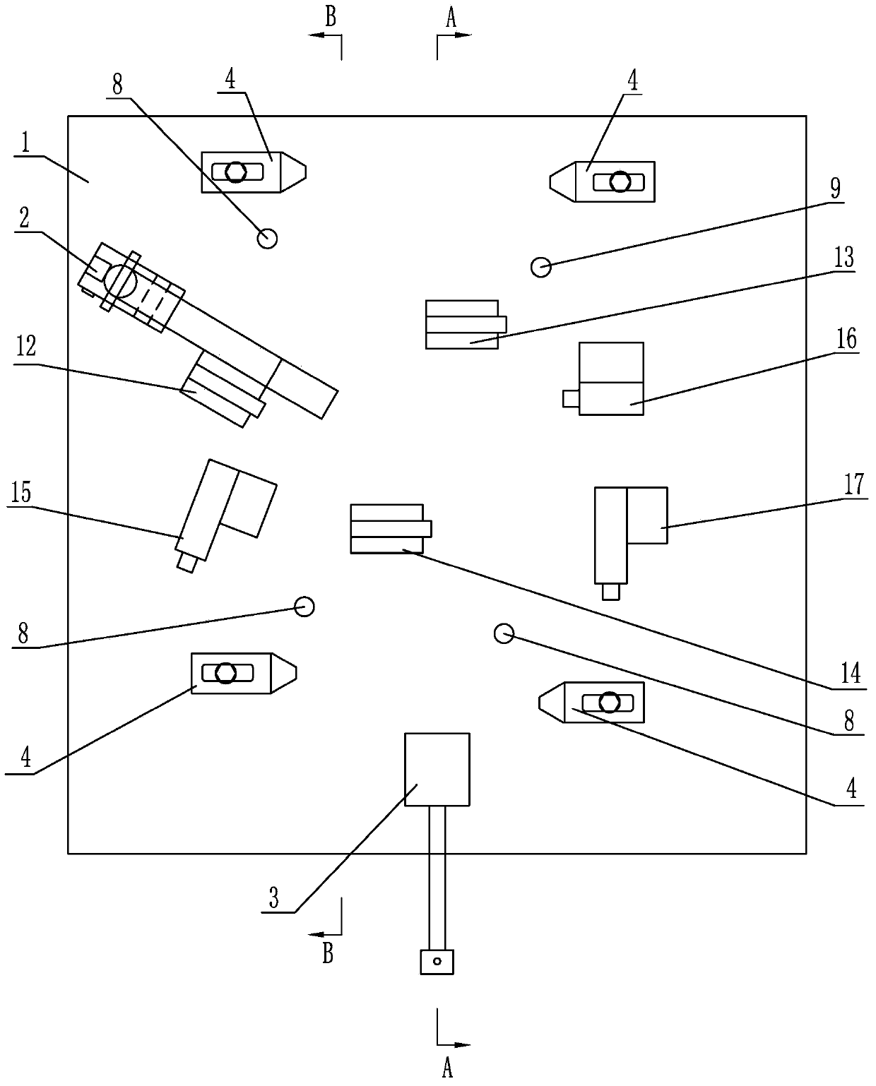
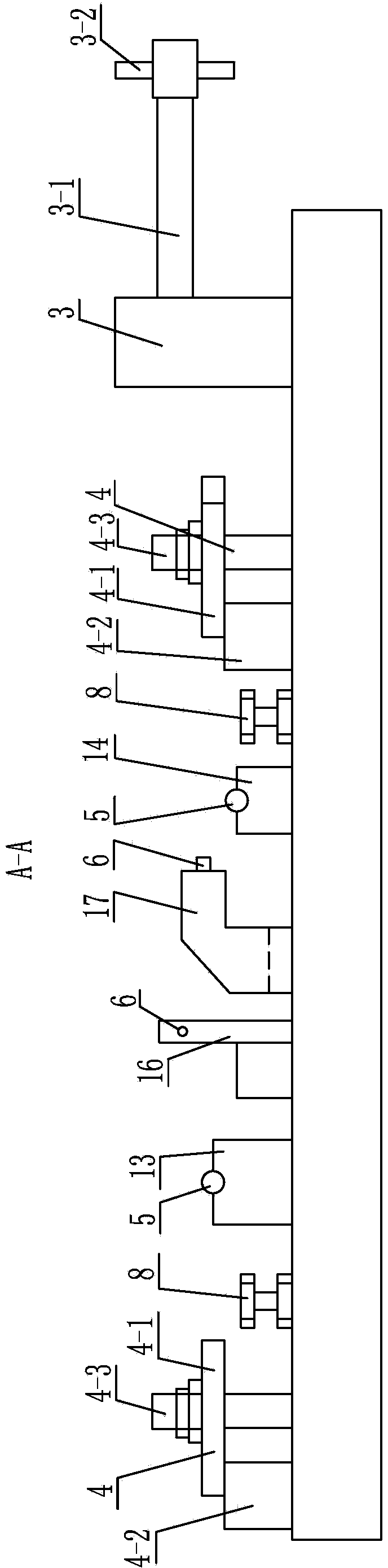
[0013] Specific implementation mode one: combine Figure 1-Figure 5 Explain that a clamping and positioning device for processing the reference plane of a gas turbine power turbine guide vane in this embodiment includes a clamping body 1, a first tightening device 2, a second tightening device 3, three positioning cylindrical pins 5, and three positioning pins. Round pin 6, four auxiliary lift adjustment support devices 8, four pressing devices 4 and six positioning seats;

[0014] Six positioning seats comprise the first positioning seat 12, the second positioning seat 13, the third positioning seat 14, the fourth positioning seat 15, the fifth positioning seat 16 and the sixth positioning seat 17; the first positioning seat 12, the second positioning seat The seat 13, the third positioning seat 14, the fourth positioning seat 15, the fifth positioning seat 16 and the sixth positioning seat 17 are correspondingly installed on the upper end surface of the clamp body 1 accordin...

specific Embodiment approach 2

[0021] Specific implementation mode two: combination figure 1 Note that the clip body 1 described in this embodiment is a square clip body. With such arrangement, the structure is simple and the design is reasonable. Others are the same as in the first embodiment.

specific Embodiment approach 3

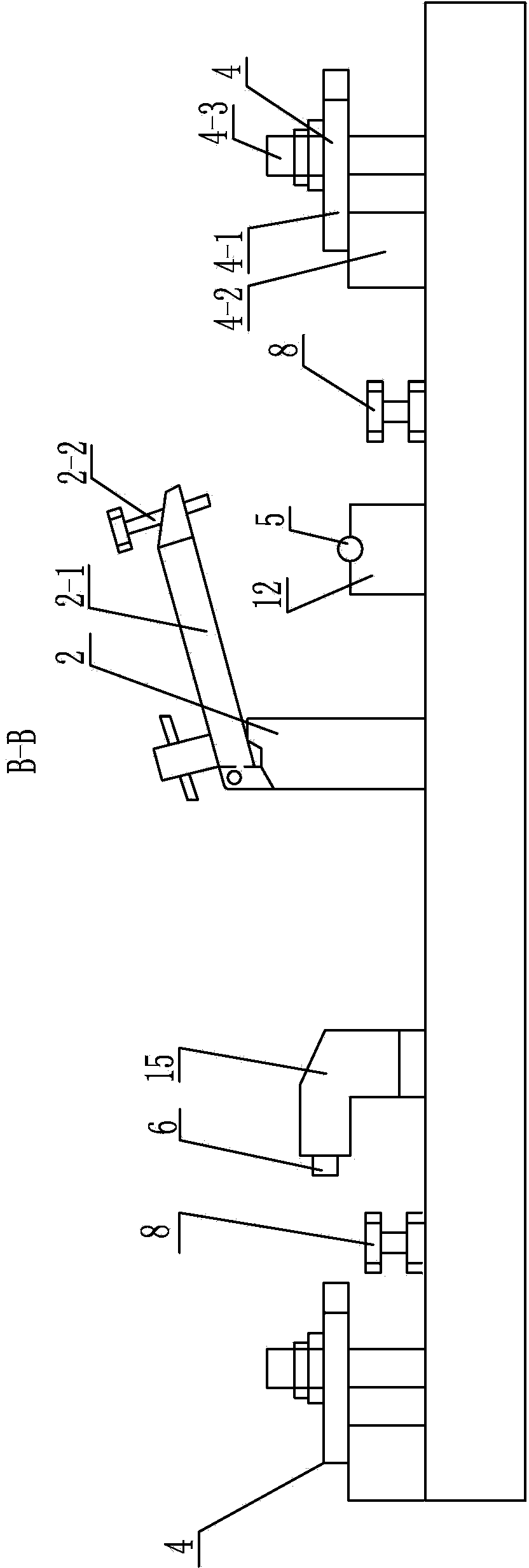
[0022] Specific implementation mode three: combination image 3 Note that the first tightening device 2 described in this embodiment includes a first tightening block 2-1 and a first bolt 2-2, and the first tightening block 2-1 is obliquely installed on the upper end surface of the clamp body 1, The first bolt 2-2 is screwed on the high end of the first tightening block 2-1. With such arrangement, the tightening of the first bolt is beneficial to the tightening and positioning of the guide vane blank of the gas turbine power turbine, which is convenient and reliable in use. Others are the same as in the first embodiment.


PUM


Abstract

The invention provides a clamping and positioning device for machining a gas turbine power turbine guide vane datum face, and relates to the clamping and positioning device. The clamping and positioning device aims to solve the problems that no special fixture device exists in the existing machining process of gas turbine power turbine guide vanes, assembling and positioning of steam passages are inconsistent with assembling and positioning of steam passage circular arcs, and the steam passages are damaged. The clamping and positioning device comprises a fixture, a first screwing device, a second screwing device, three positioning cylindrical pins, three positioning round head pins, four auxiliary lifting adjusting and supporting devices, four pressing devices and six positioning bases. The first positioning base, the second positioning base, the third positioning base, the fourth positioning base, the fifth positioning base and the sixth positioning base are correspondingly installed on the upper end face of the fixture according to the positions of six datum points for machining workblanks of the gas turbine power turbine guide vanes. The first screwing device, the second screwing device, the four pressing devices and the four auxiliary lifting adjusting and supporting devices are arranged on the upper end face of the fixture. The clamping and positioning device is used for positioning and machining of the gas turbine power turbine guide vanes.

Description

technical field [0001] The invention relates to a clamping and positioning device, which belongs to the technical field of steam turbine processing. Background technique [0002] Gas turbine power turbine guide vanes are precision casting blades with special materials, high hardness, special shape, and large steam passage surface. Its assembly is based on the positioning of the working part of the steam passage after pouring and processing of other assembly parts, including blade roots, Blade crown, inlet and outlet steam side planes, etc., in processing and assembly, it is also necessary to ensure that the steam passage of the working part (the steam passage will not be processed after pouring) is consistent. The processing reference plane includes the difference between the blade root and the blade top steam outlet plane The processing of the outer arc process has a certain influence on its position relative to the steam channel. Therefore, it is necessary to position the...

Claims


Application Information

Patent Timeline
Patent Type & Authority Applications(China)
IPC IPC(8): B23Q3/00
CPCB23Q3/00B23Q2703/10
Inventor 李辉李强黄守滨闫智宏刁建平徐玉宝柴晓辉张义彬胡春利
Owner HARBIN TURBINE
Why Eureka
Try Eureka