Shower room floor drainage skid resistance structure
A shower room, ground technology, applied in drainage structures, floors, waterway systems, etc., can solve the problems of bath water seepage through the ground and walls, insufficient water accumulation prevention ability, and lack of attention, to enhance the anti-slip effect, Anti-slip effect enhanced, fast drying effect
- Summary
- Abstract
- Description
- Claims
- Application Information
AI Technical Summary
Problems solved by technology
Method used
Image
Examples
Embodiment 1
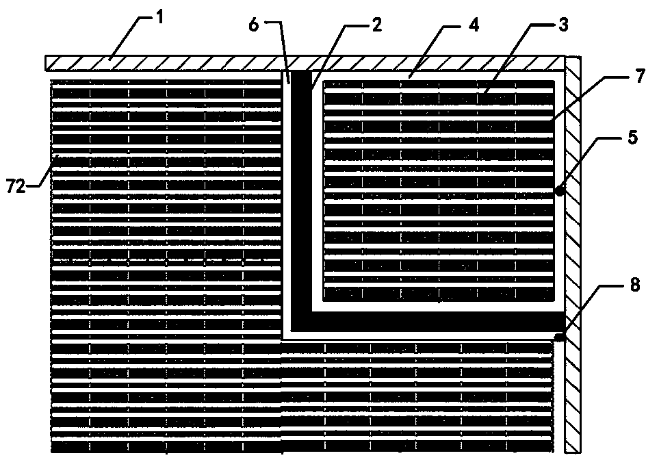
[0043] Such as figure 1 As shown, a floor drainage anti-slip structure of a shower room includes a wall 1, a partition 2, and the partition 2 isolates the shower room in the toilet, and a shower floor 3 is arranged in the middle of the shower room, and the shower floor 3 and the wall 1 Between, and between the shower floor 3 and the partition 2, an annular drainage ditch 4 is provided, and a floor drain 5 is arranged in the annular drainage ditch 4. The water generated during bathing will flow from the shower floor 3 to the annular drainage ditch 4, And then flow to floor drain 5 and discharge. There is also a water blocking ditch 6 outside the partition, and a spare floor drain 8 is also provided in the water blocking ditch 6. When the floor drain of the shower room in the partition is blocked, water accumulates, or the partition is damaged or other conditions cause the shower room to When the internal accumulated water overflowed, the overflowed water could flow to the wate...
Embodiment 2
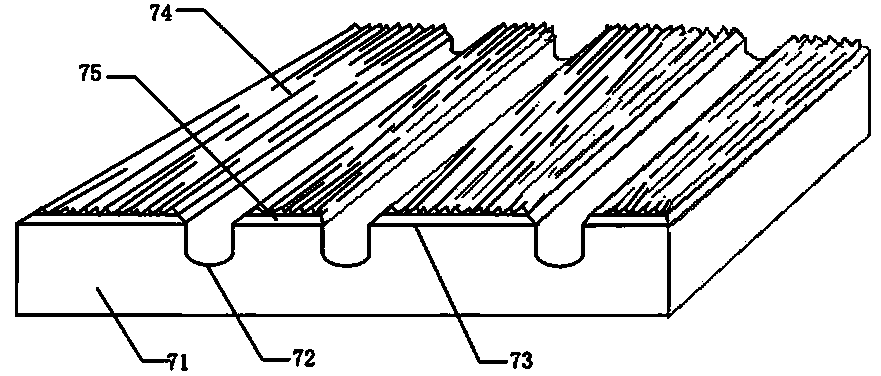
[0048] The difference between this embodiment and Embodiment 1 is that non-slip floor tiles 7 are laid on the shower floor 3 and / or other floors of the toilet outside the shower room. Such as figure 2 to figure image 3 As shown, the anti-slip floor tile 7 includes a brick body 71, and a drainage groove 72 is opened on the brick body 71. The part of the surface of the brick body 71 except the drainage groove 72 forms a roughened anti-skid part 73, and the roughened anti-skid part The surface of 73 is napped 74, and the napped 74 is composed of a number of irregular, rough, and lengthwise textures, which is difficult to form a water film and is not easy to slip; The distance (i.e. the width of the brushed anti-slip portion 73 between adjacent drainage grooves) is set narrower, and when water falls to the floor tiles, it will quickly flow to the drainage groove, the anti-skid effect will be enhanced, and it will be more difficult to slip. It can be seen that the multifunction...
Embodiment 3
[0059] In this embodiment, on the basis of embodiment 2, the non-slip floor tile 7 is optimized and improved. Such as Figure 4 to Figure 8 As shown, shallow water grooves 76 perpendicular to the drainage groove 72 are also distributed on the surface of the napped anti-slip part 73. The arrangement of the shallow water grooves 76 helps the water on the surface of the napped anti-slip part 73 to flow along the texture of the napped part 74 to the shallow The water tank 76 then flows into the drain tank 72 and is discharged along the drain tank 72, so that the surface of the napped anti-slip part 73 is not easy to store water, is easy to dry, and can better maintain the anti-skid effect. In addition, the setting of the shallow water tank 76 is also for cleaning. The brushed anti-slip portion 73 and the floor using the anti-slip floor tile 7 create favorable conditions.
[0060] The shallow water tank is perpendicular to the drainage tank, and the drainage tank is deeper than th...
PUM
 Abstract
Description
Claims
Application Information
 - R&D
- Intellectual Property
- Life Sciences
- Materials
- Tech Scout
- Unparalleled Data Quality
- Higher Quality Content
- 60% Fewer Hallucinations
Browse by: Latest US Patents, China's latest patents, Technical Efficacy Thesaurus, Application Domain, Technology Topic, Popular Technical Reports.
© 2025 PatSnap. All rights reserved.Legal|Privacy policy|Modern Slavery Act Transparency Statement|Sitemap|About US| Contact US: help@patsnap.com


